Measure panel and module voltage
Measuring panel voltage is a common troubleshooting step when experiencing odd behavior on a panel. Most often, this step is required when there is a Modem-Panel Comm message, or the panel is not communicating properly with Alarm.com.
Note: The panel and module voltage cannot be measured on the Qolsys IQ Panel, DSC Touch, and Qolsys IQ Panel 2. For those panels, verify the power supplies used are the correct voltage.
Measuring voltage
Voltage is the change in electrical energy across some part of the circuit. To measure voltage, a voltmeter like the one in the following image is required. Voltmeters can come in all different shapes, styles, colors, and brands. There is not any particular brand that is recommended since they all should accomplish the same goal.

The next part of testing the voltage is to know what to measure. The main type of voltage that would be tested with the panels is an alternating current (AC). A direct current (DC) would be used if testing the Alarm.com module or the panel battery, and it is usually marked as V–, V---, DCV, or VDC on the voltmeter. The setting for testing voltage in an AC circuit is typically marked V~, ACV, or VAC on the voltmeter. The black probe should be in the Common jack and the red probe should be in the Voltage jack as shown in the following image.

Note: The voltage requirements and location to measure it varies from panel to panel. For more information about requirements for each panel, see the panel-specific power requirements article listed in Power requirements.
When testing panel voltage the circuit should already be closed with current flowing, meaning that everything is already wired up to the panel/module and the panel/module is powered on. Then the voltmeter should have the two probes placed at different points on the circuit to connect it in parallel with the circuit.
The following image is an example of testing the module power with a voltmeter:

Reading the voltage
Once the proper connections are made, the voltage DC or AC can be read on the voltmeter.


Important considerations
Fuses
If the voltage is not within the power requirements, the fuse can blow.
- The SEM-Honeywell/ADEMCO Vista and SEM-DSC PowerSeries require a 3 amp fuse.
- The Interlogix Concord requires a 10 amp fuse.
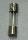
The following table displays examples of a good fuse, slightly burnt fuse, and a fuse that experienced a major short circuit:
| Good fuse | Slightly burnt | Major short circuit |
|---|---|---|
 |
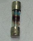 |
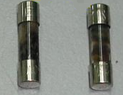 Note: Discoloration means that there is a major short circuit in the equipment. |
Wire length
The following table displays the typical maximum wire length by gauge size that can be used to connect Alarm.com cellular modules to modular panels (i.e., DSC PowerSeries Neo/Pro, Interlogix Concord, NX, System Enhancement Modules, etc.).
| Gauge | Length |
|---|---|
| 22 gauge | 40 feet (12.2 meters) |
| 18 gauge | 90 feet (27.4 meters) |
Note: Doubling wires and Cat5e cables (and its variants) are not supported. For more information about using Cat5e cables, see Can Cat5e cables be used to connect Alarm.com cellular modules to panels?.
Troubleshooting
Panel voltage
If the panel voltage is too high or too low, try the following troubleshooting steps:
- Inspect the outlet and wiring.
- Inspect the outlet for damage (e.g., signs of burning, charring, or physical damage).
- Check for loose connections. Loose or corroded connections can cause voltage drops or spikes.
- Check for overloaded circuits.
- Reduce load by unplugging other devices on the same circuit to see if the voltage stabilizes.
- Check that circuit breakers are not tripped or malfunctioning.
- Replace the transformer of the device.
- Verify the new transformer meets the panel's requirements. These requirements are typically found in the panel's installation guide.
- If the panel voltage is still too high or too low after completing the preceding steps, contact the panel manufacturer.
Module voltage
If the module voltage is too high or too low, try the following troubleshooting steps:
- Verify the wiring is correct between the module and the panel.
- Verify the wire gauge and length of run meet requirements.
- Verify power budget requirements are being met for each panel type. Panels list power budget requirements in its installation guide.
- The following panels have Power Budget Calculators available:
- If the preceding are all correct, perform the following:
- Verify the panel AC power and backup battery are within the requirements for that specific panel.
- For more information about requirements for each panel, see the panel-specific power requirements article listed in Power requirements.
- Replace the wiring between the module and the panel.
- Consider removing additional bus devices if voltage appears to be low and then check to see if it stabilizes.
- If hardware is available, test with a second module. Consider equipment availability and convenience when proceeding.
- Verify the panel AC power and backup battery are within the requirements for that specific panel.