
4MP Indoor/Outdoor Battery Spotlight Camera (ADC-V731B) - Installation Guide
Compatibility Notice: Alarm.com does not support third-party solar panels for use with Alarm.com cameras.
The Alarm.com Solar Panel (ADC-VACC-SP4W) and ADC-V731B camera are designed to be used together to ensure a weatherproof connection. The full suite of features and functionalities will only work correctly with the official Alarm.com Solar Panel.
Pre-installation checklist
- ADC-V731B camera (included)
- ADC Universal Battery Pack (included)
- Wi-Fi (2.4 or 5 GHz) connection to broadband Internet (Cable, DSL, or Fiber Optic) Internet. For information about bandwidth requirements, see What are the internet service and bandwidth requirements for Alarm.com video devices?.
-
A computer, tablet, or smartphone with Wi-Fi is required if the router does not have the Wi-Fi Protected Setup (WPS) feature
There are three options for connecting the ADC-V731B to the Wi-Fi network: Bluetooth (BLE) mode, Access Point (AP) mode or Wi-Fi Protected Setup (WPS) mode. BLE mode is the recommended method to connect the camera to the network, then AP mode if BLE mode is not possible.
Note: Some Internet Service Providers disable the WPS feature on customer routers.
In the box
- ADC-V731B camera
- ADC Universal Battery Pack
- USB-C Cable
- Installation card
- Wall mount
- Wall plate
- Wall anchors & screws (x2)
Pre-installation
Important: If the status LED indicates 20% state of charge or lower upon unboxing (i.e., the status LED is solid blue while it is not charging), it is recommended to charge the device before beginning installation to help ensure the process is completed without interruption. It is always advised to fully charge the battery immediately after installation (i.e., the status LED on the camera is solid green while charging in-unit, or the charging indicator LED on the battery pack is solid blue).
If the battery is below 10%, you will not be able to begin installation until the charge level is above 10%.
The following steps should be taken prior to the installation steps:
- Unbox the unit. Carefully remove the device and all included components from the packaging.
- To remove the battery pack:
- Press the oval button located on the bottom of the device to release the housing.
- Set the back housing aside and locate the black notch at the bottom of the battery pack.
- Press the notch inward and slide the battery pack downward to remove it.
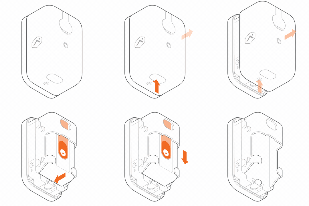
- To reinsert the battery pack:
- With the battery pack removed, carefully peel off any protective film covering the device or components.
- Align the battery pack with the cradle and slide it back into place. Make sure you hear the notch click to confirm it is securely inserted.
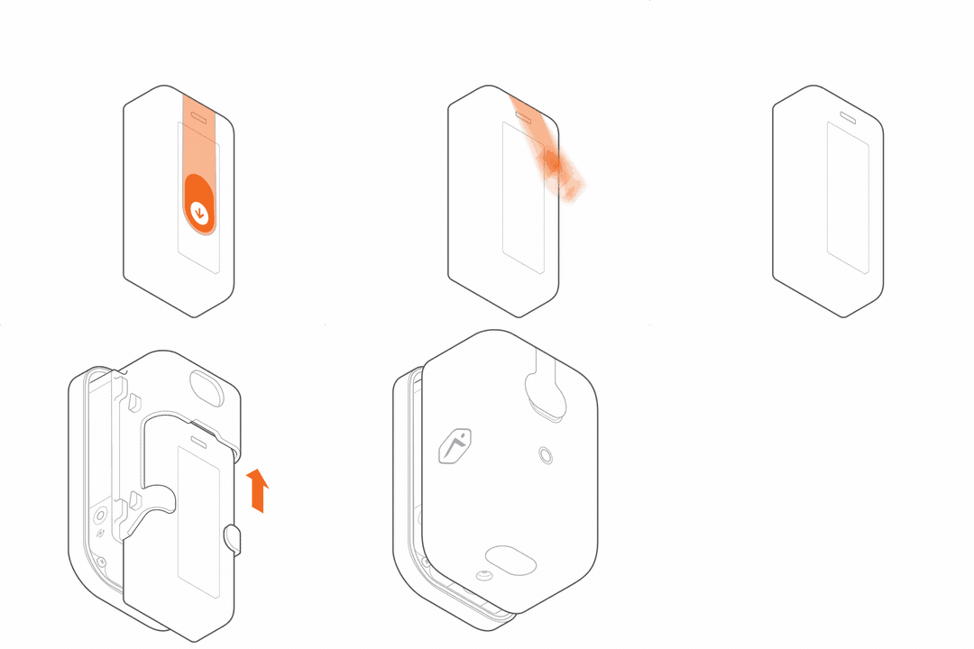
- Verify the LED indicator on the front of the device goes into pairing mode (blinking white).
- When the device turns on, it begins blinking red to indicate the device is booting.
- If the device is new or has not been previously associated with a network, the LED should begin blinking white to indicate it has entered pairing mode. If the LED is blinking white, replace the rear housing by pressing it together with the camera body, and proceed to the next section of the guide.
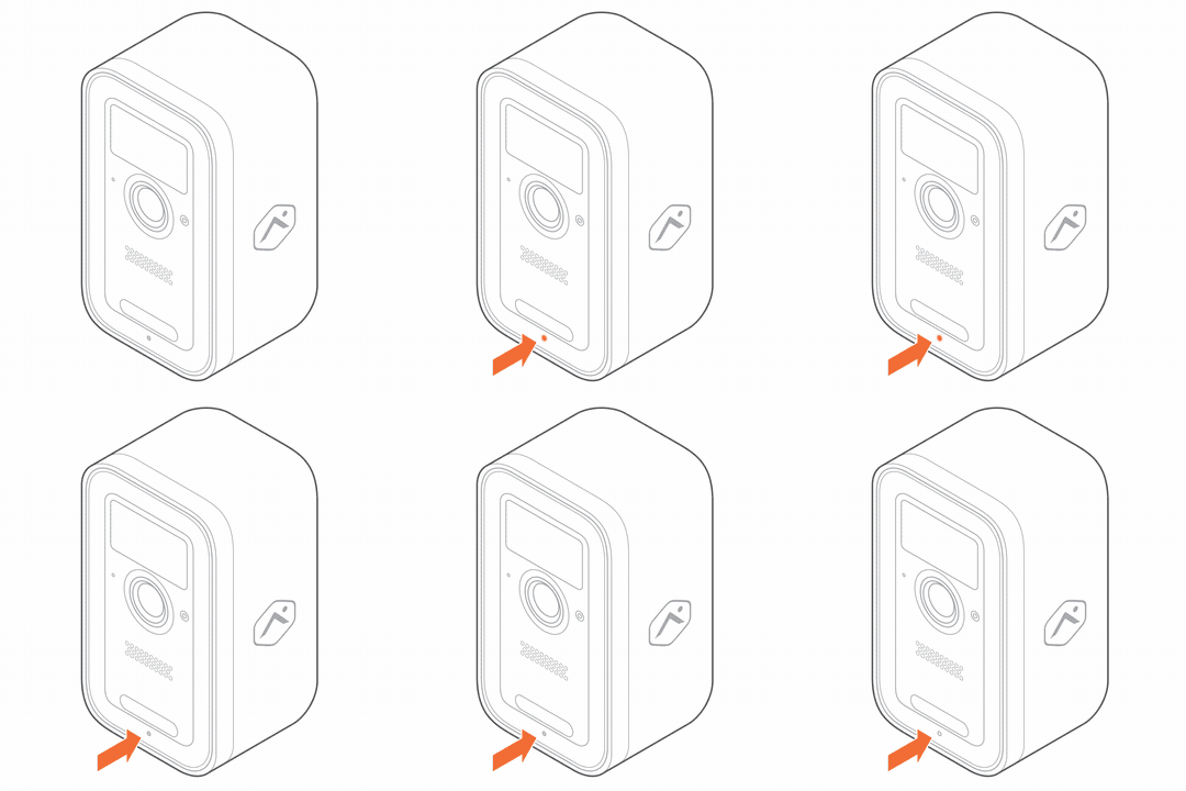
- If the LED light does not blink white, press and hold the multi-purpose button located on the side of the device (accessible once the housing is removed) for 3 seconds, or until the LED begins blinking white. Once the LED starts blinking white, release the button and proceed to the next section of the guide.
Connect the camera to the Wi-Fi network
The ADC-V731B can be connected to the Wi-Fi network using BLE mode, AP mode, or WPS mode. BLE mode is the recommended method to connect the camera to the network.
Note: An installation tutorial can also be found on the enrollment page of the Alarm.com customer website and Alarm.com app to walk through these steps.
To ensure a sufficient Wi-Fi signal, complete the following steps with the camera near its final location but prior to mounting.
BLE mode steps (recommended)
Important: BLE mode requires the ADC-V731B to be on hardware version 0401+ and firmware version 7.2.3+. The hardware version (HWV) and firmware version (FWV) are both printed on the label on the outside of the box. You can also find the hardware version printed on the camera, under the battery pack after removal.
AP mode steps
- Power on the camera. The camera’s LED will begin to blink white. If the LED is not white after two minutes, press and hold the multi-purpose button and release when the LED begins to blink white (about 3 seconds).
- Connect to the camera’s Wi-Fi network. On an Internet-enabled device, connect to the Wi-Fi network ADC-V731B (XX:XX:XX) where XX:XX:XX is the last six characters of the ADC-V731B’s MAC address, which is located on the camera or on the packaging.
- Access the camera setup page. On the same device, open a web browser and enter http://v731binstall.com or 192.168.1.1 in the URL field. Follow the on-screen instructions to add the ADC-V731B to the Wi-Fi network. During this process, the LED will briefly turn red before blinking green. The LED will turn solid green once the connection is successfully completed.
- Once the LED is solid green, proceed to Enroll the camera to the account.
WPS mode steps
- Open the camera’s housing. Press the oval button located on the bottom of the device to release the housing.
- Enter WPS pairing mode. Press and hold the multi-purpose button located on the side of the device (accessible once the housing is removed) for 6 seconds, or until the LED begins blinking blue. Once the LED starts blinking blue, release the button to enter WPS mode.
- Activate WPS mode on the router. The camera will begin to connect to the Wi-Fi network. The LED will be solid green when the connection is complete.
- Once the LED is solid green, proceed to Enroll the camera to the account.
Enroll the camera to the account
The camera can be enrolled to your customer account using the Alarm.com customer website or Alarm.com app.
Alarm.com customer website steps
- Navigate to the Video Device Setup page by entering the following URL using a web browser: www.alarm.com/addcamera. The customer's username and password for the account are required to log in.
- If the installation tutorial was used, it automatically navigates to this page after completing the tutorial.
- Enter the MAC address of the camera, then click Find.
- Enter a name for the camera, then click Install.
- Follow the on-screen instructions to finish adding the camera. An installation progress bar displays on the screen.
Alarm.com app steps
- Log in to the Alarm.com app. The customer's username and password for the account are required to log in.
- Tap
 .
. - Tap Add Device.
- Tap Video Camera.
- Tap Enter MAC Address, then enter the camera's MAC address.
- Tap Install for the camera on the Device Found page.
- Enter a device name, then tap Next.
- Follow the on-screen instructions to finish adding the camera. The installation progress displays on the screen.
Once the enrollment process is complete, move the camera to its final location. Prior to installing, verify the signal strength at the installation location using the Alarm.com app. Once the signal strength has been verified, install the device with the included hardware.
Physical installation
The ADC-V731B features standard ¼” tripod screw threading, allowing compatibility with a variety of mounting options. A wall plate and wall mount are included in the box for flush surface mounting. Alternatively, the camera can be placed directly on a flat surface or used with a variety of third-party mounts and stands. Follow the instructions below to mount the camera to a flush surface.
Note: The ADC-V731B also has a Desk Mount (ADC-VACC-731B-STND) available as an alternate mounting option. This mount can be ordered through the Partner Portal's Order Equipment page.
Camera mounting best practices
Mounting height
For best motion detection, mount the camera around 8 feet (2.5 meters) high. Placing the camera too low can lead to late or missed detections.
Camera angle
The camera works best when it is tilted down at about a 15° angle.
Harder to sense movements
The camera might have difficulty detecting objects with low heat output, like small pets. Increasing the detection sensitivity may assist, but it will also lead to quicker battery depletion.
Approach path
Avoid head-on movement. Position the camera to ensure that common approach paths cross its field of view, enabling earlier detection.

Moving objects
Keep the camera away from swaying objects or similar movements (e.g., swaying trees or vehicle traffic) to reduce battery drain.
To install the ADC-V731B in its final location:
Important: Prior to mounting, verify the signal strength using the Alarm.com app. Once the signal strength has been verified, install the device with the included hardware.
Consider recharging requirements when selecting the installation height. Make sure the person responsible for recharging can easily reach the camera and knows how to remove the battery pack.
- Mark and drill mounting holes. Use the included mounting plate to mark the desired locations for the mounting screws.
- If mounting to drywall: Drill two 3/16” holes and insert the included wall anchors.
- If mounting to wood: Drill two 1/8” holes.
- Attach the mounting plate. Align the camera’s mounting plate with the drilled holes. Use the included screws to securely fasten the plate to the mounting surface.

- Secure the mount to the plate. Align the mount with the mounting plate following the printed instructions on the plate. Turn the mount until it clicks securely into place.

- Attach the camera to the tripod screw.
- Remove the optional small security screw from the packaging and insert it into the bottom of the camera to prevent the camera and back housing from separating.
- Screw the camera onto the tripod screw threading until it is tight and securely fastened.
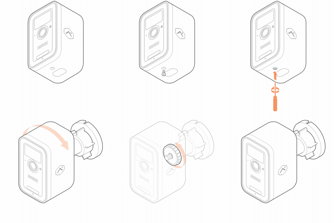
- Adjust the camera angle. Loosen the collar on the mount to adjust the ball joint. Move the camera to point toward the area you want to monitor. Once the camera is positioned correctly, tighten the collar to secure it in place.
LED reference guide
When operating on battery power, the status LED will light up in response to motion or when the camera’s state is altered (i.e., button press events, booting on, firmware upgrades, and deterrence responses).
| LED pattern | Description |
|---|---|
|
Off
|
Power off or standby |
|
Solid green
|
Connected to Alarm.com |
|
Blinking green
|
Local network connection |
|
Blinking red
|
Power on, camera booting |
|
Solid red
|
No local or internet connection |
|
Solid blue
|
Low battery |
|
Blinking white
|
Wi-Fi Access Point and Bluetooth Network Association modes (press and hold the button for 3-6 seconds) |
|
Blinking blue
|
WPS mode (press and hold button for 6-9 seconds) |
|
Blinking yellow
|
Power cycling (press and hold button for 9-12 seconds) |
|
Blinking red and green
|
Reverting to factory default settings (press and hold the button for 12-15 seconds) |
|
Blinking green and blue
|
Firmware updating |











Caution: Factory resetting the device will require it to also be deleted from the customer account and re-enrolled.
Charging
In-unit charging
| LED pattern | Description |
|---|---|
|
Blinking yellow and green
|
Charging |
|
Blinking yellow and blue
|
Charging failed |
|
Solid green
|
Charged and connected to Alarm.com |


Battery pack charging
| LED pattern | Description |
|---|---|
|
Solid red
|
Charging |
|
Blinking red and blue
|
Charging failed |
|
Solid blue
|
Charged and connected to Alarm.com |

Troubleshooting
- If you have issues connecting the camera to the account, power cycle the camera and try again.
- If issues persist, reset the camera to factory defaults. Press and hold the multi-purpose button until the LED is flashing green and red (about 12 seconds), then release the button. The camera will reboot to factory default.
Caution: Factory resetting the device will require it to also be deleted from the customer account and re-enrolled.
(Optional) Solar Panel Accessory for V731B Battery Camera (ADC-VACC-SP4W) installation
The ADC-V731B camera's USB-C connection point is designed to be waterproof when used with the ADC-VACC-SP4W solar panel. When attached, the USB-C connector fits snugly against an internal gasket, blocking water from entering. This design has passed outdoor testing to ensure your camera remains safe and functional in any weather.
Tools needed
- Drill with 3/16" drill bit (optional for wood mount)
- Screwdriver with #2 Phillips bit
Install the wall mount
The SP4W features standard ¼" tripod screw threading, allowing compatibility with a variety of mounting options. A wall mount is included in the box for flush surface mounting. Alternatively, the panel can be used with a variety of third-party mounts and stands. Follow the instructions below to mount the panel to a flush surface.
- Choose the mounting location. The solar panel needs to be mounted within 9 feet of the camera.
- Verify there are no nearby obstructions that could cause shadows on the solar panel.
- Mark and drill mounting holes. Use the included mount to mark the desired locations for the mounting screws.
- If mounting to drywall, drill two 3/16" holes.
- Attach the mount. Align the solar panel's mount with the drilled holes. Use the included screws to securely fasten the mount to the mounting surface.
- Attach the solar panel to the tripod screw.
- Screw the solar panel onto the tripod screw threading until it is tight and securely fastened.
- Adjust the solar panel angle. Loosen the collar on the mount to adjust the ball joint. Move the solar panel to align it according to your location below. Once the solar panel is positioned correctly, tighten the collar to secure it in place.
Align the solar panel
The solar panel needs to be in a sunny location that gets three or more hours of direct sunlight per day with no shadows.
For the Northern Hemisphere:
The solar panel needs to face south and be tilted to 45 degrees.
For the Southern Hemisphere:
The solar panel needs to face north and be tilted to 45 degrees.
Note: A properly oriented solar panel can charge the camera's battery up to twice as fast as a misaligned one. For more information on optimizing your solar panel installation, see Optimize Solar Panel Accessory (ADC-VACC-SP4W) installation for maximum efficiency.
Connect the solar panel to the camera
Stretch the cord from the solar panel to the camera. If you have extra cable, you can wrap it around the back side of the solar panel and use the clips to secure it. Once the cord is aligned properly and the extra is wrapped out of the way, locate the USB-C port on the back of the camera. Open the rubber dust cover and firmly insert the USB-C connector into the camera.
Review camera angle
While still logged in to the Alarm.com app or Alarm.com customer website, open the camera's live view to verify its Field of View was not unintentionally altered while the solar panel was being installed, and also to check that the solar panel is not in the camera's Field of View.
Regular Maintenance
- Review the physical installation location periodically to make sure the solar panel is still aimed correctly.
- If the panel has collected dirt or debris, remove any debris and wipe with water and a clean, soft cloth.
- Review expected charging and maximize solar charging by making adjustments to the positioning as needed.
Maximizing battery life:
Important: The camera will only charge when its battery is within a safe temperature range of approximately 32°F to 113°F (0°C to 45°C).
- Position the solar panel optimally to maximize charging efficiency.
- The camera will not charge over 80% on solar power to extend the lifetime of the battery.
- The ADC-V731B goes into a low power mode until the PIR sensor detects motion. Once the trigger is activated, the camera comes online and processes the video. The more triggers, the faster the battery will be consumed. When using the solar charging solution, it is recommended that the triggers are tuned to eliminate as many false positives as possible.
For more information about the Solar Panel Accessory (ADC-VACC-SP4W), see Solar Panel Accessory (ADC-VACC-SP4W) - Frequently Asked Questions.
Regulatory Statements
Operating Temperature: -4°F – 113°F (-20°C – 45°C)
Ingress Protection: IP65
CAUTION
- Risk of fire, explosion, burn. Do not short circuit, crush, heat above 60º C, incinerate, or disassemble the battery.
- Use only the ADC-VACC-BAT-2LIB battery.
- For outdoor charging, use the ADC-VACC-SP4W solar panel or the USB-C cable included in the camera's packaging.
- When charging via the USB-C cable, use a certified or approved power supply source and ensure that the power adaptor is protected from the elements and connected to a weather resistant outlet.
- For indoor charging, use a certified or approved power supply source and the 20W USB-C cable included in the camera's packaging (or any 20W USB-C cable capable of 12 VDC output).
FCC Statements
FCC Short Part 15 Statement
This device complies with part 15 of the FCC Rules. Operation is subject to the following two conditions: (1) This device may not cause harmful interference, and (2) this device must accept any interference received, including interference that may cause undesired operation.
FCC Long Part 15 Statement
Note: This equipment has been tested and found to comply with the limits for a Class B digital device, pursuant to part 15 of the FCC Rules. These limits are designed to provide reasonable protection against harmful interference in a residential installation. This equipment generates, uses and can radiate radio frequency energy and, if not installed and used in accordance with the instructions, may cause harmful interference to radio communications. However, there is no guarantee that interference will not occur in a particular installation.
If this equipment does cause harmful interference to radio or television reception, which can be determined by turning the equipment off and on, the user is encouraged to try to correct the interference by one or more of the following measures:
- Reorient or relocate the receiving antenna.
- Increase the separation between the equipment and receiver.
- Connect the equipment into an outlet on a circuit different from that to which the receiver is connected.
- Consult the dealer or an experienced radio/TV technician for help.
- Changes or modifications not expressly approved by the party responsible for compliance could void the user‘s authority to operate the equipment.
RF Exposure
This equipment complies with FCC and ISED radiation exposure limits set forth for an uncontrolled environment. This equipment should be installed and operated with a minimum distance of 20cm between the equipment and your body. This device and its antenna(s) must not be co-located or operating in conjunction with any other antenna or transmitter.
FCC ID
FCC ID: YL6-143V731B
ISED Statements
Condition
This device contains license-exempt transmitter(s)/receiver(s) that comply with Innovation, Science and Economic Development Canada's licence-exempt RSS(s). Operation is subject to the following two conditions:
- This device may not cause interference.
- This device must accept any interference, including interference that may cause undesired operation of the device.
The device operating in the 5150–5250 MHz band is intended for indoor use only.
Cet appareil contient des émetteurs/récepteurs sans licence qui sont conformes aux RSS sans licence d'Innovation, Sciences et Développement économique Canada. L’exploitation est soumise aux deux conditions suivantes :
- Cet appareil ne doit pas provoquer d'interférences.
- Cet appareil doit accepter toute interférence, y compris les interférences susceptibles de provoquer un fonctionnement indésirable de l'appareil.
Le dispositif fonctionnant dans la bande de fréquences 5150–5250 MHz est destiné uniquement à une utilisation intérieure.
RF Exposure
Cet appareil est conforme aux limites d'exposition aux radiofréquences établies par la FCC et l’ISED pour un environnement non contrôlé. Cet appareil doit être installé et utilisé à une distance minimale de 20 centimètres entre l’appareil et votre corps. Cet appareil et son ou ses antennes ne doivent pas être situés ou fonctionner en conjonction avec une autre antenne ou un autre émetteur.
IC ID
IC: 9111A-143V731B
Mexico IFT/CRT

- IFT #: JOALAD26-010566
- La operación de este equipo está sujeta a las siguientes dos condiciones: (1) es posible que este equipo o dispositivo no cause interferencia perjudicial y (2) este equipo o dispositivo debe aceptar cualquier interferencia, incluyendo la que pueda causar su operación no deseada.
EU Declaration of Conformity Statement
Hereby, Alarm.com Incorporated declares that the equipment type ADC-V731B is in compliance with Directive 2014/53/EU. The full text of the EU declaration of conformity is available at the following internet address:
Chile SUBTEL
Commercial information
|
Date of publication |
21/11/2025 |
|---|---|
| Commercial Name Nombre Comercial del Equipo |
Cámara con batería de 4 MP para interiores/exteriores con audio bidireccional y foco integrado |
| Manufacturer Fabricante |
Alarm.com Incorporated |
| Chile Representative Representante en Chile |
Asesorías Hernández y Grimberg Limitada Certificación Telecom |
| Chile Rep Address Domicilio |
Moneda 920, Apt. 305, Santiago, Chile RUT: 76.499.456-6 |
| Chile Rep Email Correo Electrónico de Contacto |
contacto@certificacion-telecom.cl www.certificacion-telecom.cl |
| Website Sitio Web |
www.alarm.com |
Technical information
| Equipment Type Tipo de Equipo |
Cámara de Seguridad |
|---|---|
| Brand Marca |
ALARM.COM |
| Model Name Modelo |
ADC-V731B |
| Technology Tecnología |
WLAN 2.4 GHz (IEEE 802.11 b/g/n/ax) WLAN 5 GHz (IEEE 802.11 a/n/ac/ax) BLE 2.4 GHz (IEEE 802.15.1) |
| Frequency Bandas de Frecuencias |
WLAN 2.4 GHz:
|
| Antenna Gain Ganancia de Antena |
WLAN 2.4 GHz:
WLAN 5 GHz:
BLE:
|
| EIRP PIRE |
WLAN 2.4 GHz: 26.18 dBm PIRE WLAN 5 GHz: 20.69 dBm PIRE BLE: 2402 - 2483.5 MHz: 7.05 dBm PIRE |
| Modules Módulos |
USI 8501-602820-01 Infineon 43022 Radio |
Other
| Declaration of Conformity Statement Declaración de Conformidad |
El equipo previamente individualizado cumple con las disposiciones establecidas en la Norma Técnica de Equipos de alcance reducido, aprobada por la resolución exenta N° 1.985, de 2017, de la Subsecretaría de Telecomunicaciones. |
|---|---|
| Test Reports Informe de Ensayo |
ADC-V731B - EU CE - EN301489 - BLE ADC-V731B - EU CE - EN301489 - WLAN 2.4 ADC-V731B - EU CE - EN301893 - WLAN 5 |
| Certificate Number Número de Certificado |
DO 122.035/F14 |
| Certificate SUBTEL Certificado SUBTEL |
ADC-V731B - ADC Cert - CL SUBTEL - 25 |