Door Controller (ADC-ACC1-17) - Installation Guide
The ADC-ACC1-17 Door Controller provides local decision making, event reporting, and database storage capabilities for the Alarm.com Smarter Access Control platform. Two reader interfaces provide control for one supervised physical barrier or two unsupervised physical barriers.
For UL compliance, the Power Sourcing Equipment (PSE), such as a PoE enabled network switch and/or PoE power injectors, must be UL Listed under UL294B.
Reader port 1 can accommodate a Wiegand or OSDP reader and provides LED and buzzer control. This port can alternatively utilize a two-wire RS-485 bus to connect up to eight Alarm.com expansion modules. Reader port 2 can only accommodate a Wiegand reader and provides LED and buzzer control.
Two Form-C contact relay outputs may be used to control locking hardware. The relay contacts are rated at 2A @ 30V DC, dry contact configuration. The two inputs that are provided may be used for monitoring door position switches or request-to-exit devices. Input circuits can be configured as unsupervised or supervised. The ADC-ACC1-17 requires Power over Ethernet (PoE) or 12V DC for power.
The ADC-ACC1-17 may be mounted in a 3-gang switch box; on the provided mounting plate, or in an enclosure. The supplied mounting plate has mounting holes that match the ADC-ACX1 mounting footprint.
The SRAM is backed up by a rechargeable battery when input power is removed. This battery should retain the data for a minimum of 3 days. If data in the SRAM is determined to be corrupt after power-up, all data, including flash memory, is considered invalid and is erased. All configuration and cardholder data must be re-downloaded.
The initial charge of the battery may take up to 48 hours to be fully charged.
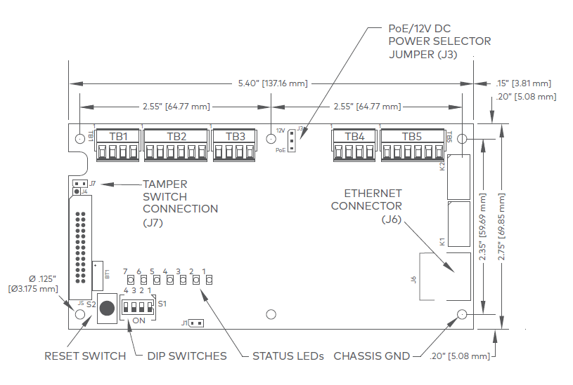
ADC-ACC1-17 hardware
Wiring and DIP switch setup
Connections
| Terminal | Label | Function |
|---|---|---|
|
TB1-1 |
IN1 | Input 1 |
| TB1-2 | IN1 | Input1 |
|
TB1-3 |
IN2 | Input 2 |
| TB1-4 | IN2 | Input 2 |
| TB2-1 | VO | Reader 1 Power Output – 12V DC |
| TB2-2 | LED | Reader 1 LED Output |
| TB2-3 | BZR | Reader 1 Buzzer Output |
| TB2-4 | CLK | Reader 1 CLK/Data 1/TR+ |
| TB2-5 | DAT | Reader 1 DAT/Data 0/TR- |
| TB2- 6 | GND | Reader 1 Ground |
| TB3-1 | LED | Reader 2 LED Output |
| TB3-2 | BZR | Reader 2 Buzzer Output |
| TB3-3 | CLK | Reader 2 CLK/Data 1 Input |
| TB3-4 | DAT | Reader 2 DAT/Data 0 Input |
| TB4-1 | VO | Auxiliary Power Output – 12V DC |
| TB4-2 | GND | Auxiliary Power Output Ground |
| TB4-3 | VIN | Input Power – 12V DC (from local power supply) |
| TB4-4 | GND | Input Power Ground |
| TB5-1 | NO | Relay K1 – Normally Open Contact |
| TB5-2 | 1-C | Relay K1 – Common Contact |
| TB5-3 | NC | Relay K1 – Normally Closed Contact |
| TB5-4 | NO | Relay K2 – Normally Open Contact |
| TB5-5 | 2-C | Relay K2 – Common Contact |
| TB5-6 | NC | Relay K2 – Normally Closed Contact |
Jumpers
| Jumpers | Set At | Description |
|---|---|---|
| J3 | PoE | ADC-ACC1-17 powered from the Ethernet connection |
| 12V | ADC-ACC1-17 powered from a local 12V DC power source connected to TB4-3 (VIN), TB4-4 (GND) |
|
| J7 | Cabinet Tamper Switch Input: short = tamper secure |
DIP switches
The four DIP switches configure the operating mode of the ADC-ACC1-17 processor. DIP switches are read on power-up except where noted. Pressing the reset button (S2) causes the ADC-ACC1-17 to reboot.
| 1 | 2 | 3 | 4 | Definitions |
|---|---|---|---|---|
| OFF | OFF | OFF | OFF | Normal operating mode. |
| ON | X | X | X | After initialization, enable default User Name (admin) and Password (password). The switch is read on the fly, no need to reboot. See IT Security section for additional information. |
| OFF | ON | X | OFF | Use installer network settings:
|
| X | X | ON | X | Disable TLS security. The controller will not interact with Alarm.com in this state. |
Note: All other switch settings are unassigned and reserved for future use.
Status LEDS
Power-up
All LEDs OFF.
Initialization
LEDs 1, 2, 3, 4, 5, 6, and 7 are sequenced during initialization. LEDs 1, 3, and 4 are turned ON for approximately 1.5 seconds after the hardware initialization has completed, then the application code is initialized. The amount of time the application takes to initialize depends on the size of the database, about 3 seconds without a card database. Each set of 10,000 cards will add about 3 seconds to the application initialization. When LEDs 1, 2, 3, and 4 flash at the same time, data is being read from or written to flash memory. Do not cycle power when in this state.
If the sequence stops or repeats, perform the Bulk Erase Configuration Memory procedure.
If clearing the memory does not correct the initialization problem, contact technical support.
Running
| LED | Description |
|---|---|
| 1 |
Connecting to Alarm.com
Note: If you are seeing an 80% OFF and 20% ON flash pattern on LED 1, the controller is OFFLINE. For assistance, see Door Controller Networking. 80% ON and 20% OFF means the controller is ONLINE. |
| 2 | Alarm.com Communication Activity |
| 3 | Readers (combined):
|
| 4 | Input IN1 Status:
|
| 5 | Input IN2 Status:
|
| 6 | Cabinet Tamper |
| 7 | Reserved |


Factory reset
The factory reset function can be used for the following purposes:
- Reset the controller back to the factory settings
- Erase any previously configured static IP settings
- Erase all configuration and cardholder database information
- Recover from database corruption causing the ADC-ACC1-17 board to continuously reboot
Factory reset steps
Caution: Do not remove power during steps 1-8.
- Set S1 dip switches to: 1 & 2 ON, 3 & 4 OFF.
- Press the reset button (S2) next to the DIP switches.
- Watch for LEDs 1 & 2 and 3 & 4 to alternately flash at a 0.5-second rate.
- Within 10 seconds of powering up, change switches 1 and 2 to OFF.
- LED 2 will flash indicating that the configuration memory is being erased.
- Full memory erase takes up to 60 seconds.
- When complete, only LEDs 1 & 4 will flash for 8 seconds.
- The ADC-ACC1-17 board will reboot 8 seconds after LEDs 1 & 4 stop flashing (no LEDs are on during this time).
Input power
The ADC-ACC1-17 may be powered one of two ways. Use jumper J3 to select the input power source:
• Power over Ethernet (PoE) connection, fully compliant to IEEE 802.3af
• Local 12V DC power supply wired to TB4-3 (VIN), TB4-4 (GND)
Reader and Expansion Module wiring
Reader port 1 can be used to wire either one Wiegand or OSDP reader or up to eight Alarm.com expansion modules. Reader port 2 can only accommodate a Wiegand reader. Power is supplied to reader port 1 at 12V DC at 180 mA maximum. The reader connected to reader port 2 may be powered from the 12V DC auxiliary power output; TB4-1 and TB4-2. Readers that require different voltage or have high current requirements should be powered separately. Refer to the reader manufacturer specifications for cabling requirements.
Reader port 1 can support up to eight Alarm.com expansion modules using a 2-wire RS-485 bus. The maximum cable length is 2,000 ft. (610 m).
For readers with two LED wires, only connect the wire controlling the green LED to the ADC-ACC1-17. When powering expansion modules and peripherals from the ADC-ACC1-17, be cautious not to exceed 650 mA @ 12V DC. 22 AWG minimum recommended for readers.
Reader wiring diagrams
Reader Port 1: Typical Wiegand Reader
Reader Port 1: Typical OSDP Reader
Reader Port 2: Typical Wiegand Reader

Reader Port 1: Wiring expansion modules using 2-wire RS-485
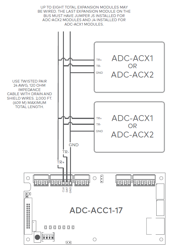
For ease of install, daisy chain expansion modules together. Wire each expansion module to the next module instead of wiring directly back to the controller.
Relay wiring
Two Form-C contact relays are provided for controlling door lock mechanisms. The relay contacts are rated at 2A @ 30V DC, dry contact configuration. Each relay has a Common pole (C), a Normally Open pole (NO), and a Normally Closed pole (NC).
When momentarily delivering power to unlock the locking hardware (i.e., Fail-Secure), the Normally Open and Common poles are used. When momentarily removing power to unlock the locking hardware (i.e., Fail-Safe), the Normally Closed and Common poles are used. Check with local building codes for proper egress door installation.
Door lock mechanisms can generate EMF feedback to the relay circuit that can cause damage and premature failure of the relay. For this reason, it is recommended that either a diode or MOV (metal oxide varistor) be used to protect the relay.
From the Auxiliary output, the ADC-ACC1-17 can provide 12V DC power for external devices, provided 650 mA is not exceeded. See the Specifications section for details. If a local power supply is used, it must be UL Listed Class 2 rated. 18 AWG minimum recommended for electric locking hardware.
Relay circuit wiring diagrams
Door strike
An electrified door strike replaces a traditional door strike for an Access Control system. Door strikes are predominantly Fail-Secure devices, meaning the door remains secure in the event power is removed. This hardware should be wired as Normally Open using an NO terminal as indicated on Fail-Secure wiring diagram above. This is because entry through the door is only granted when the controller is signaled to close the circuit which energizes the strike and allows entry.
Door lock mechanisms can generate EMF feedback to the relay circuit that can cause damage and premature failure of the relay. For this reason, it is recommended that either a diode or MOV (metal oxide varistor) be used to protect the relay. The wire should be of sufficient gauge to avoid voltage loss.
Diode selection:
Maglock
An electromagnetic lock or maglock is an electromagnet that mounts on a door frame, with a steel armature mounted on the door. Maglocks are Fail-Safe only devices. This means that when power is removed or in the event of a fire alarm input (FAI) signal the maglock unlocks the door as required by code. This hardware should be wired as Normally Closed using an NC terminal as indicated on the Fail-Safe diagram above. This is because constant flowing power is required to keep the maglock energized to secure the door.
MOV selection:
Input wiring
Inputs are used to monitor door position switches or request-to-exit devices. Input circuits can be configured as unsupervised or supervised. When unsupervised, reporting consists of only the open or closed states.
When configured as supervised, the input circuit will report not only open and closed but also open circuit, shorted, grounded*, and foreign voltage*. A supervised input circuit requires two resistors to be added to the circuit to facilitate proper reporting. The standard supervised circuit requires 1k ohm, 1% resistors, and should be located as close to the sensor as possible.
*Grounded and foreign voltage states are not a requirement of UL 294 and therefore not verified by UL.
22 AWG minimum required for input wiring. 18 AWG recommended if wiring request-to-exit devices in series with
locking hardware.
The input circuit wiring configurations shown are supported but may not be typical:

Specifications
The interface is for use in low voltage, Class 2 circuits only.
The installation of this device must comply with all local fire and electrical codes.
| Input power | PoE or 12V DC, 900 mA max |
|---|---|
| Output power | 650 mA @ 12V DC |
| Inputs | One dedicated reader input One switchable reader/two-wire RS-485 input Two programmable inputs One dedicated tamper input |
| Outputs | Two relay outputs (2A @ 30V DC) Single-wire LED control Single-wire buzzer output |
| Certifications | HSPD-12/FIPS201 compliant UL 294 and UL 294B recognized ROHS FCC Part 15 Class A NIST certified encryption |
| Dimensions (WxLxH ) | Without Bracket: 5.5 x 2.75 x 0.96” (140 x 70 x 24 mm) With Bracket: 5.5 x 3.63 x 1.33” (140 x 92 x 34 mm) |
| Temperature | 32°F – 158°F (0 – 70°C) operational -67°F – 185°F (-55 – 85°C) storage |
| Operating humidity | 10-95% (non-condensing) RH |