X1100 Door Controller (ADC-AC-X1100) - Installation Guide
 Have you taken the Smarter Access Control training course yet?
Note: This article specifically covers the installation of the X1100 Door Controller (ADC-AC-X1100). For instructions on how to set up a broader access system, see HID Aero Series Smarter Access Control - Quick Start Guide.
This course is recommended for every installer and is required for three reps per Service Provider before Access Control hardware can be added to an Alarm.com account. The course should be completed at least 48 hours before the first customer installation begins.
Already familiar with Smarter Access Control? Great! You can take the Fast Track training assessment to complete the training requirement. All training can be found at https://academy.alarm.com/page/access-control or in How can permission be granted to create Access Control accounts and order hardware?.
X1100 Door Controller
The X1100 Door Controller provides local decision making, event reporting, and database storage capabilities for the Alarm.com Smarter Access Control platform. Two reader interfaces provide control for two supervised physical barriers.
For UL compliance, the Power Sourcing Equipment must be UL Listed under UL 294.
Reader ports 1 and 2 can accommodate a reader and provide LED and buzzer control. Form-C contact relay outputs may be used to control locking hardware. The relay contacts are rated at 5 A @ 30 VDC (NO) and 3 A @ 30 VDC (NC), dry contact configuration. The four inputs that are provided may be used for monitoring door position switches or request-to-exit devices. Input circuits can be configured as unsupervised or supervised. The X1100 requires 12 to 24 VDC for power.
The SRAM is backed up by a lithium battery when input power is removed. This battery should be replaced annually. If data in the SRAM is determined to be corrupt after power-up, all data, including flash memory, is considered invalid and is erased. All configuration and cardholder data must be re-downloaded.
Jumper setup
Prior to installation, set the battery and termination jumpers.
Important: Set the battery jumper J4 to ON.
If this step is skipped, the local database will be cleared if the board experiences a drop in power.
Important: If the X1100 will be either the beginning or end of the communication bus, set the end of line termination jumpers J5 and J9 to IN. This configuration is the most common.
Leave the jumper set to OUT only if a single communication bus is wired directly to two expansion modules. This is rare and not recommended unless required to minimize wiring.
DIP switches
The four DIP switches determine the operating mode of the X1100 processor. DIP switches are read on power-up except where noted. The DIP switches are set in the normal operating position (OFF) by default. No action is required.
For information about advanced configurations, see What are the DIP switches used for on an X1100 Door Controller?.
X1100 hardware
Wiring
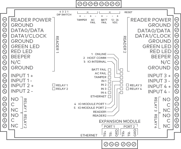
Connections
| Terminal | Label | Function |
|---|---|---|
| TB1-1 | VOUT | Reader 1 Power |
| TB1-2 | GND | Reader 1 Ground |
| TB1-3 | D0 | Reader 1 Data 0/DAT |
| TB1-4 | D1 | Reader 1 Data 1/CLK |
| TB1-5 | GND | Reader 1 Ground |
| TB1-6 | GRN | Reader 1 Green LED |
| TB1-7 | RED | Reader 1 Red LED |
| TB1-8 | BZR | Reader 1 Beeper |
| TB1-9 | N/C | No Connection |
| TB1-10 | GND | Reader 1 Ground |
|
TB2-1 TB2-2 |
IN1 | Input 1 |
|
TB2-3 TB2-4 |
IN2 | Input 2 |
| TB3-1 | NO | Relay 1 Normally Open Contact |
| TB3-2 | C | Relay 1 Common Contact |
| TB3-3 | NC | Relay 1 Normally Closed Contact |
| TB3-4 | NO | Relay 2 Normally Open Contact |
| TB3-5 | C | Relay 2 Common Contact |
| TB3-6 | NC | Relay 2 Normally Closed Contact |
| TB4-1 | VOUT | Reader 2 Power |
| TB4-2 | GND | Reader 2 Ground |
| TB4-3 | D0 | Reader 2 Data 0/DAT |
| TB4-4 | D1 | Reader 2 Data 1/CLK |
| TB4-5 | GND | Reader 2 Ground |
| TB4-6 | GRN | Reader 2 Green LED |
| TB4-7 | RED | Reader 2 Red LED |
| TB4-8 | BZR | Reader 2 Beeper |
| TB4-9 | N/C | No Connection |
| TB4-10 | GND | Reader 2 Ground |
|
TB5-1 TB5-2 |
IN3 | Input 3 |
|
TB5-3 TB5-4 |
IN4 | Input 4 |
| TB6-1 | NO | Relay 3 Normally Open Contact |
| TB6-2 | C | Relay 3 Common Contact |
| TB6-3 | NC | Relay 3 Normally Closed Contact |
| TB6-4 | NO | Relay 4 Normally Open Contact |
| TB6-5 | C | Relay 4 Common Contact |
| TB6-6 | NC | Relay 4 Normally Closed Contact |
|
TB7-1 TB7-2 |
TMP | Tamper |
|
TB7-3 TB7-4 |
AC | AC Fail |
|
TB7-5 TB7-6 |
BT | Battery Fail |
| TB7-7 | GND | Input Power Ground |
| TB7-8 | VIN | Input Power (from local supply) |
|
TB8-1 TB8-2 TB8-3 |
TR+ TR- GND |
IO Module Port 1 |
|
TB8-4 TB8-5 TB8-6 |
TR+ TR- GND |
IO Module Port 2 |
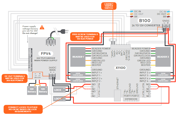
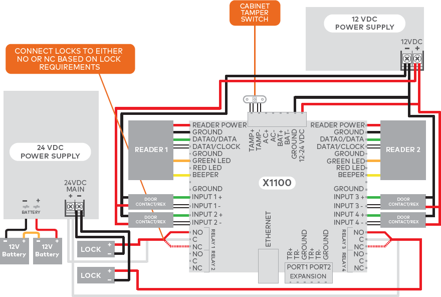
24 VDC and 12 VDC power supplies
Note: The ADC-AC-X1100 can be powered using 12 or 24 VDC (12 VDC is displayed in diagram below). To power the controller using 24 VDC, connect the 24V power supply to the GROUND and 12-14 VDC terminals instead of a 12V power supply.
For third-party power supplies:
Status LEDs
| LED | Initialization | Normal Operation |
|---|---|---|
| BATT FAIL | ON then OFF | OFF = Inactive, ON = Active, Flash = Fault* |
| AC FAIL | ON then OFF | OFF = Inactive, ON = Active, Flash = Fault* |
| TAMPER | ON then OFF | OFF = Inactive, ON = Active, Flash = Fault* |
| IN 1 | ON then OFF | OFF = Inactive, ON = Active, Flash = Fault* |
| IN 2 | ON then OFF | OFF = Inactive, ON = Active, Flash = Fault* |
| IN 3 | ON then OFF | OFF = Inactive, ON = Active, Flash = Fault* |
| IN 4 | ON then OFF | OFF = Inactive, ON = Active, Flash = Fault* |
| ONLINE | ON for ~ 15 s | Off-Line / On-Line and battery status Off-Line = 20% ON, On-Line = 80% ON Double flash if battery is low |
| HOST COMM | ON for ~ 1 s | Host communication activity (Ethernet) |
| IO INTERNAL | ON for ~ 1 s | Internal IO module communication activity |
| IO MODULE PORT 1 | ON for ~ 1 s | External IO module activity (Port 1) |
| IO MODULE PORT 2 | ON for ~ 1 s | External IO module activity (Port 2) |
| READER 1 | ON for ~ 1 s | Flashes when data is received, either input |
| READER 2 | ON for ~ 1 s | Flashes when data is received, either input |
| RELAY 1 | OFF | ON = Energized |
| RELAY 2 | OFF | ON = Energized |
| RELAY 3 | OFF | ON = Energized |
| RELAY 4 | OFF | ON = Energized |
| ETHERNET | OFF | Flashing = Ethernet Activity |
| ETHERNET JACK | OFF | Green/Left ON = Good link Yellow/Right ON = 100 Mb/s Yellow/Right OFF = 10 Mb/s |
*Note: If this input is defined, every three seconds the LED is pulsed to its opposite state for 0.1 seconds. Otherwise, the LED is OFF.
Factory reset
The Factory Reset function can be used for the following purposes:
- Erase all configuration and cardholder database information.
- Recover from database corruption causing X1100 board to continuously reboot.
- Erase any previously configured static IP settings.
Factory reset steps
- With the X1100 board powered off, set S1 DIP switches to: 1 & 2 “ON”, 3 & 4 “OFF”.
- Apply power to the X1100 board. LED 1 will turn on for about 15 seconds while the X1100 boots up.
Important: Do not remove power during the following steps: - Watch for LEDs 1 & 2 and 3 & 4 to alternately flash at a 0.5 second rate; LED 1 will be solid for 15 seconds before this occurs.
- Within 10 seconds after the above pattern starts, change switches 1 and 2 to “OFF”.
- LED 2 will flash, indicating the configuration memory is being erased. Full memory erasure takes up to 60 seconds.
- When complete, only LEDs 1 & 4 will flash for 3 seconds.
- The X1100 board will reboot 2 seconds after LEDs 1 & 4 stop flashing (no LEDs are on during this time).
Input power
The X1100 requires 12 to 24 VDC power. Connect power with minimum of 18 AWG wire.
- Connect the power ground to earth ground in only ONE LOCATION within the system. Multiple earth ground connections may cause ground loop problems and is not advised.
- Observe POLARITY on 12 to 24 VDC input (GND (-) and VIN (+)).
Cabinet tamper and UPS fault input wiring
Connect the AC FAIL (AC+/-) and BATT FAIL (BT+/-) inputs to the corresponding contacts provided on the power supply. Connect the TAMPER input to a tamper switch on the enclosure.

Reader and expansion module wiring
Reader ports
- Each port can be used to wire one Wiegand or OSDP reader.
- Readers that require different voltage or have high current requirements should be powered separately.
- Refer to the reader manufacturer specifications for cabling requirements.
| X1100 | Description |
|---|---|
| READER POWER | Reader Power 12 VDC |
| GROUND | Ground |
| D0 / DAT / B | Wiegand Data 0, Data line, OSDP B |
| D1 / CLK / A | Wiegand Data 1, Clock line, OSDP A |
| GROUND | Ground (not Shield) - Optional |
| GREEN LED | Green LED - If reader only has one LED wire, use the Green LED terminal |
| RED LED | Red LED |
| BEEPER | Beeper |
| NO CONNECTION | Not used |
| GROUND | Ground (not Shield) - Optional |
Reader wiring diagrams
Typical Wiegand reader
Typical OSDP reader
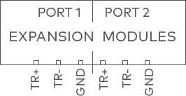
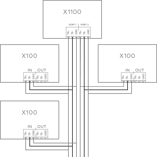
Wiring Expansion Modules
Connect up to 31 total X100 expansion modules using 2-wire RS-485 Expansion Module ports 1 and 2. The last expansion module on the bus must have the termination jumper installed. Use 1-twisted pair, shielded cable, 120Ω impedance, 24 AWG, 4,000 ft. (1,219 m) maximum total length.
Note: For ease of install, daisy chain expansion modules together. Wire each expansion module to the next module instead of wiring directly back to the controller.
 |
 |
Relay wiring
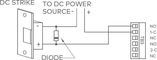
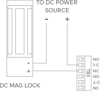
Four Form-C contact relays are provided for controlling door lock mechanisms. The relay contacts are rated at 5 A @ 30 VDC (NO), 3 A @ 30 VDC (NC), dry contact configuration. Each relay has a Common pole (C), a Normally Open pole (NO), and a Normally Closed pole (NC).
When momentarily delivering power to unlock the locking hardware (fail secure), the Normally Open and Common poles are used. When momentarily removing power to unlock the locking hardware (fail safe), the Normally Closed and Common poles are used. Check with local building codes for proper egress door installation.
Caution: Door lock mechanisms can generate EMF feedback to the relay circuit that can cause damage and premature failure of the relay. For this reason, it is recommended that a diode be used to protect the relay.
Relay circuit wiring diagrams
| Diode selection: | MOV selection: |
|---|---|
|
|
 |
 |
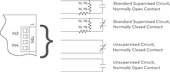
Input wiring
Inputs are used to monitor door position switches or request-to-exit devices. Input circuits can be configured as unsupervised or supervised. When unsupervised, reporting consists of only the open or closed states.
When configured as supervised, the input circuit will report not only open and closed but also open circuit, shorted, grounded,* and foreign voltage.* A supervised input circuit requires two resistors be added to the circuit to facilitate proper reporting. The standard supervised circuit requires 1k Ω 1% resistors, which should be located as close to the sensor as possible.
*Note: Grounded and foreign voltage states are not a requirement of UL 294 and therefore not verified by UL.
22 AWG minimum required for input wiring. 18 AWG recommended if wiring request-to-exit devices in series with locking hardware.
The input circuit wiring configurations shown are supported but may not be typical:
Specifications
The interface is for use in low voltage, Class 2 circuits only. The installation of this device must comply with all local fire and electrical codes.
| Input power | 12 to 24 VDC ±10%, 1.9 A max |
|---|---|
| Inputs | Two dedicated reader inputs Two independent, dedicated ports: 2-wire RS-485 Four programmable inputs One dedicated input for each of the following: Tamper, AC Fail, and Battery Fail |
| Outputs | Four relay outputs 5 A (NO) and 3 A (NC) @ 30 VDC Two-wire LED control Single-wire buzzer output |
| Certifications | FCC, CE, UL 294 Certified |
| Dimensions (W x L x H) | 6.46” x 5.51” x 1.02” (164 mm x 140 mm x 26 mm) |
| Temperature | 32°F – 158°F (0°C – 70°C) operational -67°F – 185°F (-55°C – 85°C) storage |
| Operating humidity | 5% - 85% (non-condensing) RH |
Warranty
Alarm.com warrants the product is free from defects in material and workmanship under normal use and service with proper maintenance for one year from the date of factory shipment. Alarm.com assumes no responsibility for products damaged by improper handling or installation. This warranty is limited to the repair or replacement of the defective unit.
There are no expressed warranties other than set forth herein. Alarm.com does not make, nor intends, nor does it authorize any agent or representative to make any other warranties, or implied warranties, and expressly excludes and disclaims all implied warranties of merchantability or fitness for a particular purpose. Returns must be accompanied by a Return Material Authorization (RMA) number obtained from customer service, and prepaid postage and insurance.
Notices
Liability
The Interface should only be used to control exits from areas where an alternative method for exit is available. This product is not intended for, nor is rated for operation in life-critical control applications. Alarm.com is not liable under any circumstances for loss or damage caused by or partially caused by the misapplication or malfunction of the product. Alarm.com’s liability does not extend beyond the purchase price of the product.

This device complies with part 15 of the FCC Rules. Operation is subject to the following two conditions:
- This device may not cause harmful interference.
- This device must accept any interference received, including interference that may cause undesired operation.