Smart Water Valve (ADC-SWV100) - Installation Guide
Installation precautions
- Adhere to all relevant local codes and ordinances as they pertain to the Smart Water Valve. You are required to consult local plumbing codes and have appropriate licensing for the installation of this device.
- Water shutoff valves and leak detection devices should never be installed on a fire suppression system. If a fire suppression system is present, ensure the Smart Water Valve is installed downstream of the branch leading to the fire suppression system.
- Never insert fingers or other objects into the Smart Water Valve. Inserting objects into the valve may result in damage or injury.
- The Smart Water Valve should only be powered using the supplied power adapter (supports mains voltage: 100-240 VAC ~50/60 HZ).
Important: Do not apply power to the Smart Water Valve until the unit is fully assembled.
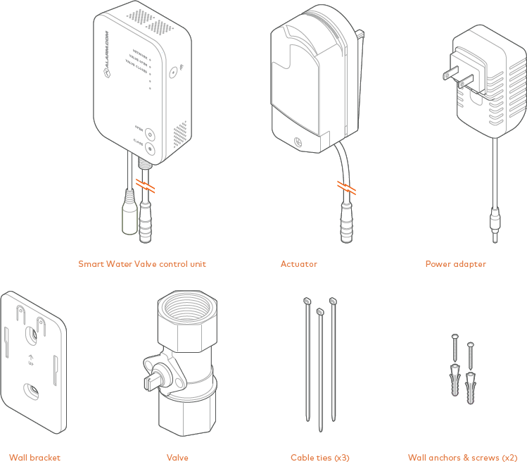
In the box
Additional parts requirements
Installation of the Smart Water Valve requires additional fittings to connect the ends of the valve to the pipe. The type of fittings needed will depend on the pipe material, industry standards, and applicable plumbing codes. Please see the Specifications section of the product packaging for more information on the pipe size and thread type of your specific Smart Water Valve. The maximum compatible pipe size is 1.25" (3.175 cm).
Buttons and LEDs
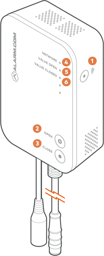
Buttons
| Name | Description |
|---|---|
(1)  |
Used for Z-Wave Add/Delete mode. This button is also used to factory reset the device. For more information, see To reset the Smart Water Valve to factory default settings. |
| (2) Open | Opens the valve. |
| (3) Close | Closes the valve. |
LEDs
| Name | Description |
|---|---|
| (4) Network |
|
| (5) Valve open |
|
| (6) Valve closed |
|
| All LEDs off | If all LEDs are off, the device has no power. |
| All LEDs flashing | All LEDs will flash for five seconds during a factory reset. |
Installation location
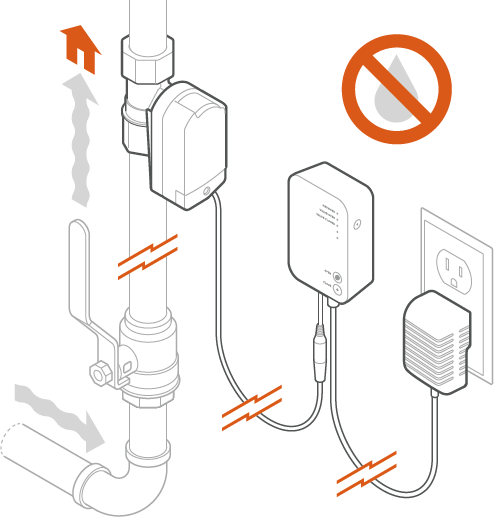
The Smart Water Valve must be installed:
- In a dry, indoor location.
- Downstream from the main shut-off valve on the desired water supply line.
- With the control unit located above the valve. Use drip loops wherever possible to avoid damaging the electronics in the event of a leak.
- In compliance with all local plumbing and electrical codes.
- Within 20 feet of a wall outlet. It is recommended to use an outlet with a ground fault circuit interrupter (GFCI).
- So that it is easily visible and accessible.
- On water main distribution pipes 1 inch or less. For installation on larger pipe diameters, please review local plumbing codes, water demand, and hydraulic performance to ensure varying pipe sizes are compatible.
Note: Water shutoff valves and leak detection devices should never be installed on a fire suppression system.
Installation
To install the Smart Water Valve:
- Shut off the water supply line and drain the system.
- Install the valve in the desired water supply line using appropriate fittings. For more information about choosing a location, see Installation location.
- After installing the valve, turn the water supply on and ensure there are no leaks originating from the valve or connections to the valve.
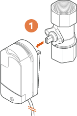
Note: If soldering fittings or adapters, use caution to ensure that the valve is not damaged by excess heat. Remove the valve from the fittings prior to soldering, if possible. - Use a wrench or actuator to move the valve stem so that it is parallel to the valve. Line up the posts on the actuator with the holes on the valve. Connect the actuator to the valve by pressing on the actuator until it snaps into place.
Note: It may be necessary to align the valve stem prior to attaching the actuator. Place the actuator on the valve stem and rotate until the posts on the actuator line up with the holes on the brass valve.

- Connect the actuator to the control unit using the attached cable. The connector is keyed to ensure proper alignment.
- Mount the control unit to the wall using the supplied wall bracket and anchors.
- Connect the power supply to the locking barrel connector on the control unit. Turn counterclockwise to lock.
- Plug the power supply into the nearest wall outlet. Verify power by checking if the LEDs are illuminated.
To test the Smart Water Valve:
- Open a tap or faucet downstream of the Smart Water Valve.
- Press the Close button and wait for the Smart Water Valve closed light to turn solid. Check that the valve has closed by verifying that no water is flowing from the open fixture.
- Press the Open button and wait for the valve open light to turn solid. Check that the valve has opened by verifying that water is flowing from the open fixture.
- Close the open tap or faucet.
- Add the Smart Water Valve to the Z-Wave network.
To add the Smart Water Valve to the Z-Wave network:
Note: For best results, it is recommended to bring the Z-Wave controller into the area where the Smart Water Valve is installed.
- Put the Z-Wave controller into add mode. For panel-specific information, refer to the relevant guides in Panels.
- Press the Network
 button on the side of the Smart Water Valve control unit to begin the add process. The network light on the control unit will begin flashing.
 - After the Smart Water Valve is successfully added, the network light on the Smart Water Valve will turn solid. If the network light is not illuminated after the add process, repeat steps 1 and 2.
Troubleshooting
The Smart Water Valve is not communicating with the Z-Wave controller.
- Perform a network communication test by pressing the button. The Network LED will blink slowly while the Smart Water Valve attempts to communicate with the Z-Wave controller. This communication test may take up to 1 minute. If the test is successful, the device will sound one long tone and the Network LED will turn solid. If the test is unsuccessful, the device will sound three short tones and the Network LED will begin to blink intermittently until communication is restored.
- If step 1 is unsuccessful, verify that the Z-Wave controller is powered on and connected. If it is not, restore power and connectivity to the Z-Wave controller and repeat step 1.
- If step 2 does not resolve the issue, try removing the device from the network (see To remove the Smart Water Valve from the Z-Wave network) and re-adding it to the network.
- If step 3 does not resolve the issue, we recommend installing a Z-Wave repeater nearby and performing a Z-Wave network rediscovery.
Note: Any wall-powered Z-Wave device will act as a repeater and improve the range between the Z-Wave controller and the Z-Wave device you are installing.
The actuator is moving, but no command (local or remote) was sent to close the valve
The actuator has two built-in features to extend the life of the actuator and ball valve. The actuator will perform a small movement periodically to ensure that the valve is fully open or fully closed, based on the state of the device.
Additionally, the actuator performs a 15-second valve check daily to ensure there are no restrictions in the motion of the ball valve. Both operations are expected behavior and will not restrict the flow of water.
To remove the Smart Water Valve from the Z-Wave network:
Note: For best results, it is recommended to bring the Z-Wave controller into the area where the Smart Water Valve is installed.
- Put the Z-Wave controller into remove mode. For panel-specific information, refer to the relevant guides in Panels.
- Press the button on the side of the Smart Water Valve control unit to begin the remove process. The network light on the control unit will begin flashing.
- The network light will turn off if the remove process is successful. If the network light is still illuminated after the removal process, repeat steps 1 and 2.
To reset the Smart Water Valve to factory default settings:
Caution: Resetting the Smart Water Valve to its factory default settings will remove the device from the network and restore all user settings to their default values.
- Press and hold the button for 10 seconds.
- All three LEDs will blink until the factory reset is complete. When the reset is complete, the LEDs turn off, and only the Valve Open or Valve Closed LED is illuminated.
Manual valve actuation
In the event of a power loss or system failure, the Smart Water Valve can be manually actuated using the following procedure:
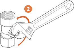
- Remove the actuator from the valve by pulling the actuator away from the valve.
- Use pliers, an adjustable crescent wrench, or a flat-head screwdriver to move the valve stem to the correct position, as shown below.
Notices
FCC
This device complies with part 15 of the FCC Rules.
Operation is subject to the following two conditions:
- This device may not cause harmful interference.
- This device must accept any interference received, including interference that may cause undesired operation.
Note: Changes and Modifications not expressly approved by Alarm.com can void your authority to operate this equipment under Federal Communications Commissions rules.
This equipment has been tested and found to comply with the limits for a Class B digital device, pursuant to part 15 of the FCC Rules. These limits are designed to provide reasonable protection against harmful interference in a residential installation. This equipment generates, uses and can radiate radio frequency energy and, if not installed and used in accordance with the instructions, may cause harmful interference to radio communications. However, there is no guarantee that interference will not occur in a particular installation. If this equipment does cause harmful interference to radio or television reception, which can be determined by turning the equipment off and on, the user is encouraged to try to correct the interference by one or more of the following measures:
- Reorient or relocate the receiving antenna.
- Increase the separation between the equipment and receiver.
- Connect the equipment into an outlet on a circuit different from that to which the receiver is connected.
- Consult the dealer or an experienced radio/TV technician for help.
For more information about Alarm.com's Water Management solution, water sensors, and water features, see Water Management - Frequently Asked Questions.
ICC
This device complies with NSF 61 and NSF 372 of the ICC-ES-PMG Rules. The ICC Evaluation Service (ICC-ES PMG) is the premier product certification program for North America, certifying Plumbing, Mechanical and Fuel Gas products to the requirements of International, Uniform and Canadian Codes and Standards.