
Climax Gen2 Hybrid - Data Sheet
Notice: Installation and maintenance servicing for this device should only be performed by qualified personnel.
This data sheet includes specifications for the Climax Gen2 Hybrid panel.
Design specifications
System functions
|
Number of partitions |
2 |
|
|---|---|---|
| Number of wired/wireless zones |
80 per partition, 160 in total Wireless and wired sensors, as well as the wired BUS devices, all count towards the total zone count. Examples of maxed out sensor count:
|
|
| Number of available ports for wired sensors | 16 on Hybrid, capable of expanding up to 64 with expansion boards | |
| Number of BUS devices | 128 | |
|
Number of PIR cameras |
16 max limit (3-5 recommended) |
|
|
Number of wired keypads (KP-35-COMBO) |
4 (via RS-485 connection) |
|
|
Number of users |
40 total users with multi-partition access |
|
|
User PIN Codes |
1 PIN Code each user (4 or 6-digits, number 0-9) Available combinations:
Note: Input of 5 invalid User PIN codes at the remote keypad will lock the remote keypad for 15 minutes. |
|
|
Wired input |
|
|
|
Ethernet Interface |
RJ-45 connection |
|
Electrical
|
External AC/DC adaptor |
12VDC/2A |
|
|---|---|---|
|
Built-in power unit |
Input: variable per region
Output: 12VDC/2A |
|
|
Auxiliary output |
12V/400mA (max.) |
|
|
PGM output |
Currently not supported |
|
|
Backup Battery |
Backup battery options:
|
|
|
Battery duration |
|
|
Wireless
|
LTE Frequency |
|
|
|---|---|---|
|
3G Frequency |
|
|
|
RF Frequency |
868.6375MHz / 433.82MHz / 426MHz / 910 MHz |
|
|
Antenna type |
On board (Z-Wave */ Wi-Fi / RF), External (4G Optional) * Only available on select Hybrid panels |
|
|
RF encryption |
Private Encryption Method |
|
|
RF protocol |
Climax F1 |
|
|
Z-Wave Frequency |
800 series Z-wave Note: This is only available on select Hybrid panels |
|
|
Wi-Fi |
|
|
|
DECT Module |
Reserved |
|
Physical Properties
|
Operating temperature |
-10°C to 45°C (14°F to 113°F) |
|
|---|---|---|
|
Operating humidity |
85% relative humidity @23°C (non-condensing) |
|
|
Dimensions |
268 mm x 320 mm x 80 mm |
|
Hybrid diagrams
Top cover front view:
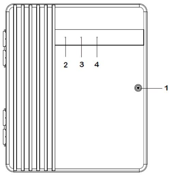
Back cover (internal view):
_of_Hybrid_.png?revision=1)
- Cover Fixing Screw
- LED 1 - Area 1 (Green/Red)
- Full Arm mode - Red lighting up
- Home/1/2/3 mode - Red flashing
- Learning mode - Green lighting up
- Walk Test mode - Green flashing
- LED 2 - Area 2 (Green/Red)
- Full Arm mode - Red lighting up
- Home/1/2/3 mode - Red flashing
- Learning mode - Green lighting up
- Walk Test mode - Green flashing
- LED 3 - Status (Orange/Red)
- System Fault - Orange lighting up
- Alarm Trigger – Red flashing
- Alarm in Memory – Red lighting up
- Removable Protective Cover x 4 (at top and bottom of the back cover)
- Removable cover to reveal or hide cable wiring hole.
- Room for Battery Pack
- Room for installing NiMH rechargeable battery pack of Hybrid-Panel-3-23/45 models.
- Mounting Holes x 4
- Wiring Clip x 4
- LED Board Connector
- EGND Terminal
- Connect the EGND terminal and the grounding wire for building's electrical installation.
- J24 Jumper Switch
- By configuring the J24 jumper settings, the PGM port can be a voltage output port or a dry contact relay output.
- RS485 Terminal
- Connect to a hardwired keypad (KPT-35-Combo), or wired expansion module (WEZC-8/WEPC-1/WEZ Series).
- Bell Terminal
- Connect to a wired bell box for bell wiring.
- PGM Port
- To be used as a voltage output port or a dry contact relay output depending on J24 jumper settings.
- Alternative Hole for Wiring Management x 2
- Built-in Power Unit (Input: 16 ~ 18VAC 40VA or 100-240VAC)
- AC module built-in power unit or Open Frame built-in power unit is installed. Use the built-in power unit to connect to the mains power.
- Ensure to turn off all power supplies including Built-in Power Unit and NiMH Battery before connecting or removing cables or wires.
- Wire Saddle
- To be used for securing power cables.
- NiMH Battery Connector
- Connect to 7.2V 4500mAh or 2300mAh NiMH rechargeable battery pack.
- Battery Switch
- Switch to "ON" for the battery to be charged when AC power is connected and serve as a backup power source when AC power is missing.
- Built-in Power Unit Connector
- Zone Terminal & 12V Auxiliary Voltage Output Terminal & GND Terminal
- Zone 1-16 Hardwired Input Zones, supporting up to 400mA for all hardwired zones, auxiliary output and KPT-35-COMBO.
- 4G-LTE External Antenna Terminal
- For connecting external antenna to the panel.
- Do not disconnect the internal antenna when connecting the external antenna. To switch between the use of internal or external antenna, please configure through software setting. See Climax Gen2 Hybrid Panel - Installation Guide.
- Internal Antenna PCBA
- Learn Button
- To be used for local learning or local reset.
- Tamper
- USB Port (optional)
- When connecting a USB dongle into the port, it is suggested to use a USB extension cable. There is no USB Port for the panel if it is built in 4G and Wi-Fi.
- Micro-SIM Card Socket (not hot swappable)
- Ethernet Port
- Room for Zone Expansion Module (12, 24, 36, or 48 zone, WEZ-12/24/36/48 expansion module, not hot swappable)
- J53 Jumper Switch
- J53 Jumper Switch can be served as a terminating resistor, which can be turned to ON when wiring different devices to the panel to enhance connection.
- U-shaped Grommet x 4
- To be used to replace the Removable Protective Cover to enhance wiring and cord management flexibility. Ensure to save the Protective Cover removed for future use.
- Velcro Tape x 4 (loop side)
- To be applied to the battery pack for easy battery installation and connection.
- In-line Tube Fuse Holder