
Climax Gen2 HSGW - Data Sheet
This data sheet includes specifications for the Climax Gen2 HSGW panel.
Specifications
System functions
|
Number of partitions |
2 |
|
|---|---|---|
|
Number of wireless zones |
80 per partition, 160 in total |
|
|
Number of PIR cameras |
16 (3-5 recommended) |
|
|
Number of users |
40 total users with multi-partition access | |
|
Zone Types |
See Appendix D of the Installation Guide |
|
|
User PIN Codes |
1 PIN Code each user (4 or 6-digits, number 0-9) Available combinations:
Note: Input of 5 invalid User PIN codes at the remote keypad will lock the remote keypad for 15 minutes. |
|
|
Control Facilities |
Remote Keypad & Remote Controller |
|
|
Report Destinations |
20 Monitoring Stations or mobile number |
|
|
Reporting Format |
Contact ID, SIA, SMS Text |
|
|
Arming Modes |
Arm Away, Arm Stay, Disarm |
|
|
Alarm Type |
Burglar, Panic, Fire, Medical, Emergency, Water, Silent |
|
|
Siren Timeout |
Programmable (3 min. by default), For Remote Keypad use only |
|
|
Supervision |
Programmable time frame for inactivity alert |
|
|
Special Function |
Tamper Protection |
|
|
GSM Standards |
Compiles with CE standards 4GPP TS 51.010-1, EN 301 511, EN301489-7 |
|
|
EN Classification |
EN Grade 2 Class II |
|
|
Alarm Transmission Path |
Dual Path: DP1 (EN50136-1:2012) |
|
|
Supported RCT |
Alarm Report Server (ARS), Fibro, OH200, MasterMind, Manitou, MicroKey and SIA DC 09 |
|
|
Mode of Acknowledgement Operation. |
Pass-through (EN50136-2:2013, Clause 6.1.3) |
|
|
Memory |
DDR3L SDRAM: 512Mbyte eMMC : 4GByte |
|
Electrical
|
Power Source |
Built-in switching power supply (S.P.S), 100-240V, 50/60Hz input, 12V 1.5A output |
|
|---|---|---|
|
Power Supply Type |
PS Type A, not suitable for use external to supervised premises |
|
|
Backup Battery |
7.2V, NiMH 600mAh AAA rechargeable battery pack (built-in) |
|
|
APS fault Low Voltage SD signal threshold |
7.3 V ± 3% |
|
|
Battery Duration |
14 hours |
|
|
Battery Recharge Time to 80% of 600mAH |
72 hours |
|
|
Minimum Energy Level of Backup Battery |
86% |
|
| Current AC Powered Drain |
Average.
|
|
| Current Battery Power Drain |
Average.
|
|
Wireless
|
GSM/GPRS/EDGE Frequency |
B1 (2100 MHz) / B3 (1800 MHz) / B5 (850 MHz) / B7 (2600 MHz) / B8 (900 MHz) / B20 (800 MHz) (EU) | |
|---|---|---|
|
LTE Frequency |
B1 (2100 MHz) / B3 (1800 MHz) / B5 (850 MHz) / B7 (2600 MHz) / B8 (900 MHz) / B20 (800 MHz) (EU) | |
|
RF Frequency |
868.6375MHz / 433.82MHz / 426MHz / 910 MHz | |
|
Z-Wave Frequency |
800 series Z-Wave Important: This is only available on select HSGW panels. |
|
|
Antenna Type |
|
|
|
Encryption |
Private Encryption Method |
|
|
Protocol |
Climax |
|
Physical Properties
|
Operating Temperature |
-10°C to 45°C (14°F to 113°F) |
|
|---|---|---|
|
Humidity |
50 ~ 85% relative humidity @23°C, non-condensing |
|
|
Size |
185mm x 185mm x 50mm |
|
|
Weight |
580g (Includes backup battery) |
|
HSGW diagrams
Front cover view

The following table describes what is in the preceding HSGW front cover view diagram.
| Number in diagram | Description |
|---|---|
| 1 |
LED 1 - Area 1 (Green/Red)
|
| 2 |
LED 2 - Area 2 (Green/Red)
|
| 3 |
LED 3 - Status (Orange/Red)
|
| 4 | Speaker |
Side view
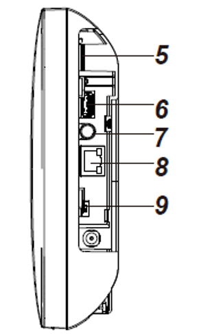
The following table describes what is in the preceding HSGW side view diagram.
| Number in diagram | Description |
|---|---|
| 5 | Micro SIM Card Compartment |
| 6 | USB Port |
| 7 | Learn/Reset Button |
| 8 | Ethernet Port |
| 9 | Battery Switch (slide to “ON” to meet requirements of the applicable EN standard.) |
Back view
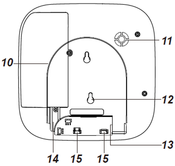
The following table describes what is in the preceding HSGW back view diagram.
| Number in diagram | Description |
|---|---|
| 10 | Internal Cover |
| 11 | Buzzer |
| 12 |
Tamper Switch
|
| 13 | Power Cord Inlet |
| 14 | Wiring Hole |
| 15 | Fixing Screws x 2 |
Mounting bracket

The following table describes what is in the preceding HSGW mounting bracket diagram.
| Number in diagram | Description |
|---|---|
| 16 | Wall Mounting Holes x 2 |
| 17 | Mounting Bracket |