Smart Water Valve+Meter (ADC-SWM150) - Installation Guide
Service package requirements
The Smart Water Valve+Meter (ADC-SWM150) requires both the Water Management and Water Management Plus service package add-ons to support advanced flow monitoring features such as Unexpected Water Activity alerts, Water Flow Shut-off rules, and water consumption display.
For information about how to update the service package on an account, see Update the service package on a customer account.
Installation precautions
- Adhere to all relevant local codes and ordinances as they pertain to the Smart Water Valve+Meter. You are required to consult local plumbing codes and have appropriate licensing for the installation of this device.
- Water shutoff valves and leak detection devices should never be installed on a fire suppression system. If a fire suppression system is present, ensure that the Smart Water Valve+Meter is installed downstream of the branch leading to the fire suppression system.
- Never insert fingers or any other item into the valve. Inserting objects into the valve may result in damage or injury.
- The Smart Water Valve+Meter should only be powered using the supplied power adapter (supports mains voltage: 100-240 VAC ~50/60 Hz).
- Take note of the Device Specific Key (DSK) and QR code located on the back of the control unit and product packaging. These are used to quickly and securely add the device to a Z-Wave network compatible with Z-Wave Security 2 (S2) and/or SmartStart.
Important: Do not apply power to the Smart Water Valve+Meter until the unit is fully assembled.
In the box

Pipe sizing
For ADC-SWM150
Pipe size 1” - thread type MNPT
For ADC-SWM150-EU
Pipe size ¾” - thread type MBSPP
Additional parts requirements
Installation of the Smart Water Valve+Meter requires additional fittings to connect the ends of the valve+meter to the pipe. The type of fittings needed depends on the pipe material, pipe size, threading type, industry standards, and applicable plumbing codes. The maximum compatible pipe size is 1.25" (3.175 cm).
LEDs and Buttons
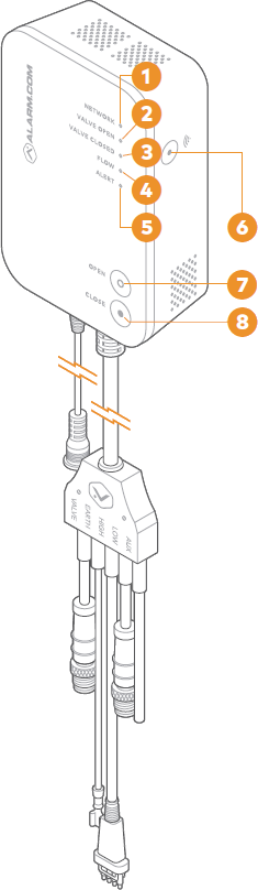
LEDs
| Name | Description |
|---|---|
| (1) Network |
|
| (2) Valve open |
|
| (3) Valve closed |
|
| (4) Flow |
|
| (5) Alert |
|
| All LEDs off | If all LEDs are off, the device has no power. |
Buttons
| Name | Description |
|---|---|
(6) Network  |
Used for Z-Wave Add/Delete mode. This button is also used to factory reset the device. For more information, see To reset the Smart Water Valve+Meter to factory default settings. |
| (7) Open | Opens the valve. |
| (8) Close | Closes the valve. |
Installation location
Note: Water shutoff valves and leak detection devices should never be installed on a fire suppression system. If a fire suppression system is present, ensure the Smart Water Valve+Meter is installed downstream of the branch leading to the fire suppression system.
The Smart Water Valve+Meter must be installed:
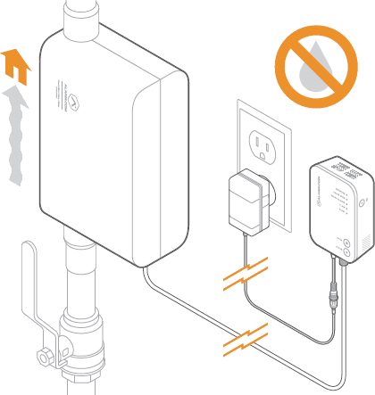
- In a dry, indoor location.
- Downstream from the main shutoff valve and, if present, the pressure reducing valve.
- As close to the main shut-off valve as possible. The Smart Water Valve+Meter only monitors water activity downstream of the device.
- On a straight run of pipe approximately 14 inches (35 cm) long. The Smart Water Valve+Meter can be installed in smaller spaces by rerouting the plumbing.
- In compliance with all local plumbing and electrical codes.
- Within 20 feet of a wall outlet. It is recommended to use an outlet with a ground fault circuit interrupter (GFCI).
- On water main distribution pipes 1 inch or less (ADC-SWM150) or ¾ inch or less (ADCSWM150-EU). For installation on larger pipe diameters, please review local plumbing codes, water demand, and hydraulic performance to ensure varying pipe sizes are compatible.
- With the control unit located above the valve+meter. Use drip loops wherever possible to avoid damaging the electronics in the event of a leak.
- So that it is easily visible and accessible.
Note: The Smart Water Valve+Meter features a backflow preventer. Ensure that there is adequate distance between the Smart Water Valve+Meter and the home’s hot water heater to allow for the expansion caused by the hot water heater. Additionally, consider installing an expansion tank downstream of the Smart Water Valve+Meter. It is not recommended to install the Smart Water Valve+Meter directly on the water heater supply line.
Installation
Installing the Smart Water Valve+Meter
- Shut off the water supply line and drain all water from the plumbing system.
- Install the valve+meter in the water supply line using the appropriate fittings. See Installation location for more information on choosing a location.
Important: Ensure that the device is installed in the correct orientation. An arrow embossed on the valve+meter indicates the correct direction of water flow.Note: If soldering fittings or adapters, use caution to ensure that the valve+meter is not damaged by excess heat. Remove the valve+meter from the fittings prior to soldering, if possible. - After installing the valve+meter, slowly turn on the main water supply and ensure there are no leaks originating from the valve+meter, connections, or surrounding pipes.
- Connect the cable harness to the valve+meter.
- Connect the black VALVE cable to the actuator and tighten the screw connector to ensure a secure connection.

- Connect the green GROUND cable to the ground cable connection on the valve+meter.

- Connect the black HIGH cable to the high flow sensor and ensure that the tabs on the connector are fully engaged on the flow sensor.

- Connect the red LOW cable to the low flow sensor and tighten the screw connector to ensure a secure connection.
Note: The blue AUX cable is reserved for future use. It is recommended to leave this cable disconnected.

- Connect the black VALVE cable to the actuator and tighten the screw connector to ensure a secure connection.
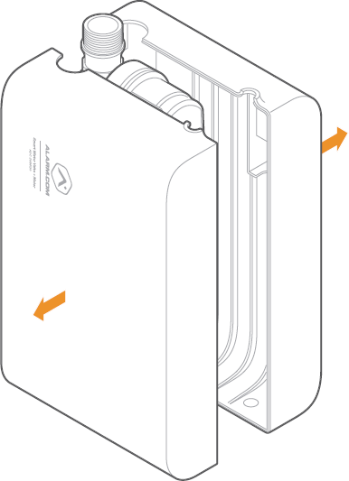
- Install the enclosure (space permitting).
- Attach SIDE A of the enclosure onto the valve+meter by clipping the valve+meter into the clips.

- Secure the cable harness by inserting it into the cable harness holder on SIDE A of the enclosure. Ensure that all cables are inside the enclosure and connected properly.
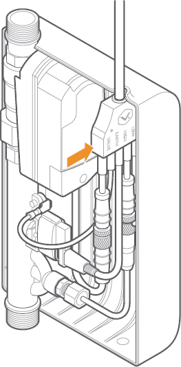
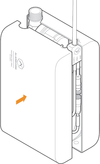
- Attach SIDE B of the enclosure to SIDE A. When properly aligned, the two sides of the enclosure snap together using the integrated magnetic clasps.
- Attach SIDE A of the enclosure onto the valve+meter by clipping the valve+meter into the clips.
- Use the included wall bracket and anchors (if applicable) to mount the control unit above the valve+meter, making sure the LEDs and buttons are visible and easily accessible.
- Connect the power supply to the power supply connection on the control unit. Tighten the lock screw to secure the connection.
- Plug the power supply into the nearest nonswitched wall outlet. Verify that the Smart Water Valve+Meter is powered by checking that either the Valve Open or Valve Closed LED is illuminated on the control unit. If no LEDs are illuminated, try a different power outlet.
- Test the Smart Water Valve+Meter to make sure it opens, closes, and detects flow (see Test the Smart Water Valve+Meter).
- Add the Smart Water Valve+Meter to the network (see Adding the Smart Water Valve+Meter to the Z-Wave network).
To test the Smart Water Valve+Meter:
- Fully open a tap or faucet downstream of the Smart Water Valve+Meter.
- Press the Close button and wait for the Valve Closed LED to turn solid.
- Check that the valve has closed by verifying that no water is flowing from the fixture opened in step 1.
- Verify that the Flow LED is not illuminated, indicating water has stopped flowing.
- Press the Open button and wait for the Valve Open LED to turn solid.
- Check that the valve has opened by verifying that water is flowing from the fixture opened in step 1.
- Verify that the Flow LED is illuminated when water is flowing.
- Close the tap or faucet opened in step 1.
- Verify that the Flow LED is not illuminated, indicating water has stopped flowing.
To add the Smart Water Valve+Meter to the Z-Wave network:
Important: For best results, it is recommended to bring the Z-Wave controller into the area where the Smart Water Valve+Meter is installed during enrollment.
As a SmartStart device:
It is recommended to enroll this device as a SmartStart device to eliminate the need to put Z-Wave controllers into Add Mode or to trigger devices (as is the case when enrolling non-SmartStart S2 devices).
For information about SmartStart compatibility and the enrollment process, see Add or remove a Z-Wave SmartStart-enabled device.
As an S2 device:
If the Z-Wave controller is not SmartStart-compatible, it is recommended to enroll this device as an S2 device for enhanced security and encryption features.
For information about this process, see Add an S2-encrypted Z-Wave device.
As an S0 device:
- Put the Z-Wave controller into add mode. For panel-specific information, refer to the relevant guides in Panels.
- Press the Network
 button on the side of the Smart Water Valve+Meter control unit to begin the Add process. The Network LED on the control unit will begin flashing.
 - After the Smart Water Valve is successfully added, the network light on the Smart Water Valve will turn solid. If the Network LED is not illuminated after the add process, repeat steps 1 and 2.
Troubleshooting
The Flow LED is blinking
The Flow LED is used to indicate a system hardware failure or other operation that may impact the performance of the Smart Water Valve+Meter. The number of blinks and blink patterns can be used to diagnose the failure or operation.
- 2 blinks: High flow sensor failure
- 3 blinks: Low flow sensor failure
- 4 blinks: Actuator failure
- Steady blink: Low flow calibration in progress
Note: It can take up to 24 hours for low flow calibration to complete after installation.
The Smart Water Valve+Meter is sounding an alarm
The Smart Water Valve+Meter is equipped with a buzzer that can be configured to sound an alarm when a flow or temperature event is detected.
This alarm is designed to inform the homeowner of a flow or temperature event in the plumbing system. It is extremely important to inspect the plumbing for any leaks before considering the alert resolved.
To locally silence the buzzer during an active unexpected flow event:
Press and hold the Close button for 5 seconds.
Important: This action does not close the valve. To close the valve, quickly press the Close button once.
To silence the buzzer from the Customer Website or app during an active unexpected flow event:
- Log in to the Customer Website or app.
- Click Fix It on the trouble condition alert.
- Click Pause the Buzzer.
The Smart Water Valve+Meter is not communicating with the Z-Wave controller
- Perform a network communication test by pressing the Network button. The Network LED will blink slowly while the Smart Water Valve+Meter attempts to communicate with the Z-Wave controller. If the test is successful, the device will sound one long tone and the Network LED will turn solid. If the test is unsuccessful, the device will sound three short tones and the Network LED will begin to blink intermittently until communication is restored.
- If step 1 is unsuccessful, verify that the Z-Wave controller is powered on and connected. If it is not, restore power and connectivity to the Z-Wave controller and repeat step 1.
- If step 2 does not resolve the issue, try removing the device from the network (see To remove the Smart Water Valve+Meter from the Z-Wave network) and re-adding it to the network.
- If step 3 does not resolve the issue, we recommend installing a Z-Wave repeater nearby and performing a Z-Wave network rediscovery.
Note: Any wall powered Z-Wave device will act as a repeater and improve the range between the Z-Wave controller and the Z-Wave device you are installing.
The actuator is moving, but no command (local or remote) was sent to close the valve
The actuator has two built-in features to extend the life of the actuator and ball valve. The actuator will perform a small movement periodically to ensure that the valve is fully open or fully closed, based on the state of the device.
Additionally, the actuator performs a 15-second valve check daily to ensure there are no restrictions in the motion of the ball valve. Both operations are expected behavior and will not restrict the flow of water.
To remove the Smart Water Valve+Meter from the Z-Wave network:
Note: For best results, it is recommended to bring the Z-Wave controller into the area where the Smart Water Valve+Meter is installed.
- Put the Z-Wave controller into remove mode. For panel-specific information, refer to the relevant guides in Panels.
- Press the Network button on the side of the Smart Water Valve+Meter control unit to begin the remove process. The Network LED on the control unit will begin flashing.
- The Network LED will turn off if the removal process is successful. If the Network LED is still illuminated after the removal process, repeat steps 1 and 2.
To reset the Smart Water Valve+Meter to factory default settings:
Caution: Resetting the Smart Water Valve+Meter to its factory default settings will remove the device from the network and restore all user settings to their default values.
- Press and hold the Network button for 10 seconds.
- All three LEDs will blink until the factory reset is complete. When the reset is complete, the LEDs turn off, and only the Valve Open or Valve Closed LED is illuminated.
Manual valve actuation
In the event of a power loss or system failure, the Smart Water Valve+Meter can be manually actuated using the following procedure:
- Remove the enclosure (if present).
- Remove the actuator from the valve by pulling the actuator away from the valve+meter, keeping the actuator parallel to the valve+meter.
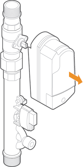
-
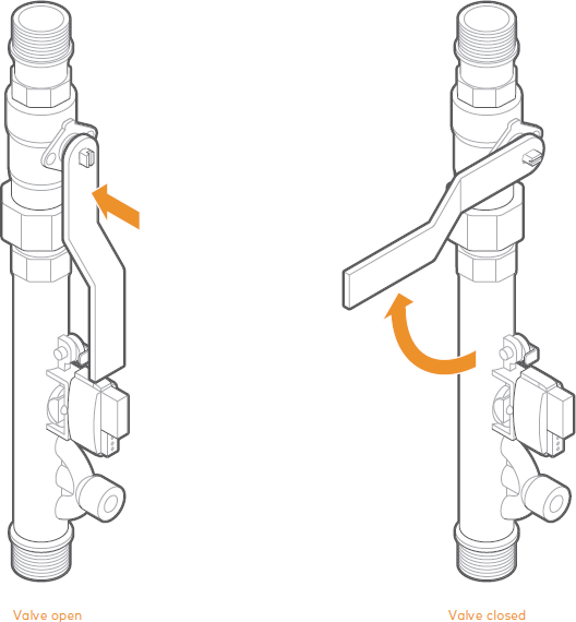
Use the valve wrench provided (attached to the inside of side B of the enclosure), a pair of pliers, adjustable crescent wrench, or flat head screwdriver to move the valve stem to the desired position, as shown below.
Additional troubleshooting
For additional troubleshooting information, see Smart Water Valve+Meter (ADC-SWM150) - Troubleshooting Guide.
Notices
Federal Communication Commission (FCC) interference statement
This device (ADC-SWM150) complies with part 15 of the FCC Rules.
Operation is subject to the following two conditions:
- This device may not cause harmful interference.
- This device must accept any interference received, including interference that may cause undesired operation.
Note: Changes and Modifications not expressly approved by Alarm.com can void your authority to operate this equipment under Federal Communications Commissions rules.
This equipment has been tested and found to comply with the limits for a Class B digital device, pursuant to part 15 of the FCC Rules. These limits are designed to provide reasonable protection against harmful interference in a residential installation. This equipment generates, uses and can radiate radio frequency energy and, if not installed and used in accordance with the instructions, may cause harmful interference to radio communications. However, there is no guarantee that interference will not occur in a particular installation. If this equipment does cause harmful interference to radio or television reception, which can be determined by turning the equipment off and on, the user is encouraged to try to correct the interference by one or more of the following measures:
- Reorient or relocate the receiving antenna.
- Increase the separation between the equipment and receiver.
- Connect the equipment into an outlet on a circuit different from that to which the receiver is connected.
- Consult the dealer or an experienced radio/TV technician for help.
IC statement
This device (ADC-SWM150) complies with Industry Canada license-exempt RSS standard(s). Operation is subject to the following two conditions:
- This device may not cause interference, and
- This device must accept any interference, including interference that may cause undesired operation of the device.
Le présent appareil (ADC-SWM150) est conforme aux CNR d’Industrie Canada applicables aux appareils radio exempts de licence. L’exploitation est autorisée aux Deux conditions suivantes :
- l’appareil ne doit pas produire de brouillage, et
- l’utilisateur de l’appareil doit accepter tout brouillage radioélectrique subi, même si lebrouillage est susceptible d’en compromettre le fonctionnement.
FCC/ISED radiation exposure statement
Hereby, Alarm.com declares that the radio equipment type the device has been found to be compliant to the requirements set forth in CFR 47 Sections 2.1091 and Industry Canada RSS-102 for an uncontrolled environment. The antenna(s) used for this transmitter must be installed to provide a separation distance of at least 20 cm from all persons and must not be co-located or operating in conjunction with any other antenna or transmitter.
Le dispositif a été jugé conforme aux exigences énoncées dans les articles 47 CFR 2.1091 et Industrie Canada RSS-102 pour un environnement non contrôle’. L’antenne(s) utilisée pour ce transmetteur doit etre installé pour fournir une distance de séparation d’au moins 20 cm de toutes les personnes et ne doit pas être co-localisés ou fonctionner en conjunction avec une autre antenne ou transmetteur.
CE notice
Hereby, Alarm.com declares that the radio equipment type ADC-SWM150-EU is in compliance with Directive 2014/53/EU. The full text of the EU declaration of conformity is available at the following internet address: https://www.alarm.com/about/international/eu-red
Frequency: 868.42 MHz | Output Power: 2 mW
Questions?
For more information about Alarm.com's Water Management solution, water sensors, and water features, see Water Management - Frequently Asked Questions.