
Alarm.com Premium Video Doorbell Camera (ADC-VDB775) - Installation Guide
Pre-installation checklist
- ADC-VDB775 with included accessories
- Wired compatible mechanical chime or digital chime (if desired)
- Wired chime installations:
- AC transformer (16-24 VAC, 10-40 VA) or DC power supply (18-24 VDC, 12-30 W)
- Alarm.com Mechanical Chime Dongle (ADC-VDBA-MCD) for wired mechanical chime installations
- Alarm.com VDB775 Power Module (ADC-VDBA-775-PM) for wired digital chime installations (sold separately)
- No wired chime installations:
- AC transformer (16-24 VAC, 10-40 VA)
- 10W 10 Ohm Video Doorbell Power Resistor (ADC-VDBA-RES-10W-10OHM) (sold separately in packs of 10) for AC transformers rated 16-24 VAC, 30-40 VA
- Mechanical Chime Dongle (ADC-VDBA-MCD) for AC transformers rated 16-24 VAC, 30-40 VA
- DC power supply (15-24 VDC, 8-20 W)
- AC transformer (16-24 VAC, 10-40 VA)
- Wi-Fi (2.4 or 5 GHz) connection to broadband Internet (Cable, DSL, or Fiber Optic)
- A computer, tablet, or smartphone with Wi-Fi is required
There are three options for connecting the ADC-VDB775 to the Wi-Fi network:
- Bluetooth Enrollment (BLE) mode
- Access Point (AP) mode
- Wi-Fi Protected Setup (WPS) mode
In the box
Note: The ADC-VDB775 also includes wall anchors (x2), ST3.5 x 22mm screws (x2), and wire terminal screws (x2)
ADC-VDB775 doorbell camera

ADC-VDB775 mounting hardware

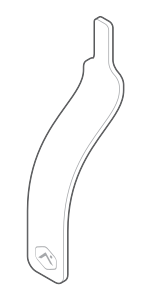

Mechanical Chime Dongle (ADC-VDBA-MCD)

Installation card with scannable QR code

Install the ADC-VDB775
Physical installation:
- Turn off power to the doorbell circuit (transformer). The recommended transformer rating is 16-24 VAC, 10-40 VA.
- Remove any existing power module from the in-home chime belonging to the video doorbell that is being replaced.
- Verify that the chime wire terminals are connected to one wire run from the transformer and one wire run from the doorbell.
- Select the in-home wired chime type below for installation steps.
Mechanical chime
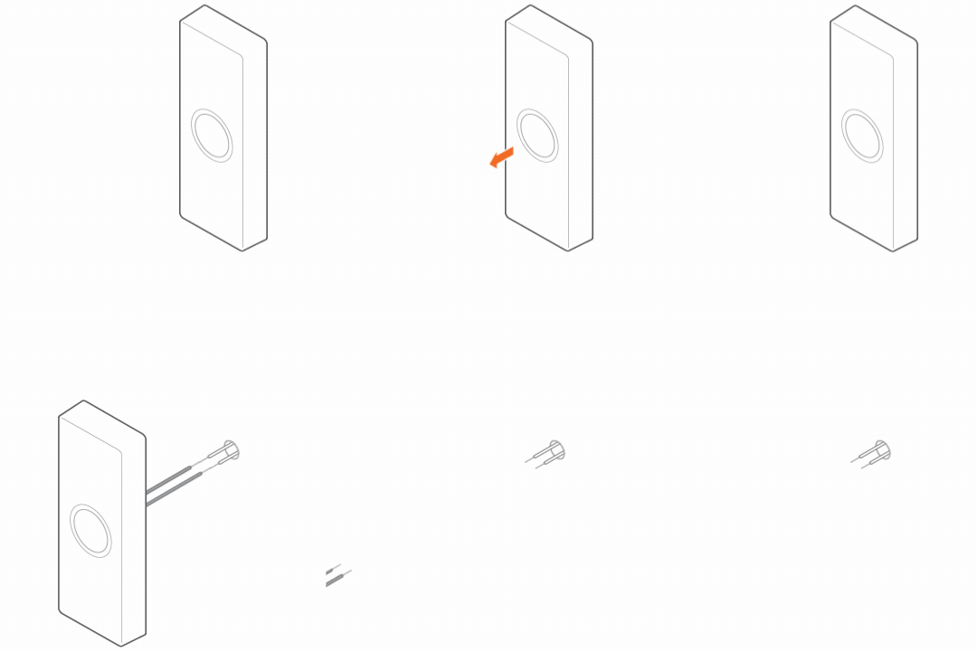
Connect the Mechanical Chime Dongle to the chime by connecting one wire to each of the terminals (i.e., FRONT and TRANS or REAR and TRANS), leaving the existing wires in place. Polarity does not matter.

Digital chime
Important: The ADC-VDB770 Power Module (ADC-VDBA-PM) is not compatible with the ADC-VDB775.
Connect the Alarm.com VDB775 Power Module (ADC-VDBA-775-PM) to the chime by connecting one wire to each of the terminals (leaving the existing wires in place).

No wired chime
Important: A 10 W, 10 ohm resistor with 5% tolerance (ADC-VDBA-RES-10W-10OHM) and Mechanical Chime Dongle (ADC-VDBA-MCD) are required for installations with no wired chime and an AC transformer with a power rating between 16-24 VAC, 30-40 VA.
For 16-24 VAC, 10-29 VA:
Attach both wires from the AC transformer to the terminals on the back of the ADC-VDB775 (polarity does not matter).
For 16-24 VAC, 30-40 VA :
- Attach either one of the wires on the Mechanical Chime Dongle to either one of the wires coming from the transformer (polarity does not matter).
- Attach the other wire from the Mechanical Chime Dongle to either one of the wires on the ADC-VDB775 (polarity does not matter).
- Attach the other wire from the ADC-VDB775 to the remaining wire coming from the transformer.
- Attach one end of the 10 W, 10 ohm resistor with 5% tolerance to the wire shared between the transformer and the Mechanical Chime Dongle, and attach the other end of the resistor to the wire shared between the Mechanical Chime Dongle and the ADC-VDB775. This wires the resistor in parallel with the Mechanical Chime Dongle.
Note: For additional compatible wiring setups and in-depth instructions, see ADC-VDB775 wiring guide.
- Select the in-home wired chime type below for installation steps.
- Remove the existing doorbell from the wall and disconnect the wires. Secure the wires so that they can be connected in a later step (you can tape them to the wall so they don't fall back into the wall).
- Verify the Video Doorbell installation height is less than 2 meters (6’ 7”) from floor level and in a vertical orientation.
- Determine whether to secure the wallplate to the optional Wedge Mount Kit (ADC-VDBA-775-WMK) or mount it directly to the surface. If mounting on an uneven surface, it is recommended to use the Wedge Mount Kit or wall spacers (ADC-VDBA-WS) to ensure the wallplate is firmly secured to the mounting surface. Select the mounting method below to see installation steps.
Direct surface mounting steps
Note: If using the wall spacers (ADC-VDBA-WS), remove the black rubber wall spacers from the clear film and firmly attach one spacer near each screw hole on the back of the wallplate (i.e., between the wallplate and the mounting surface).
- Thread doorbell wires through wallplate, making sure to thread wires underneath plastic bridges of wallplate leading to screw terminals, and secure to wallplate screw terminals.
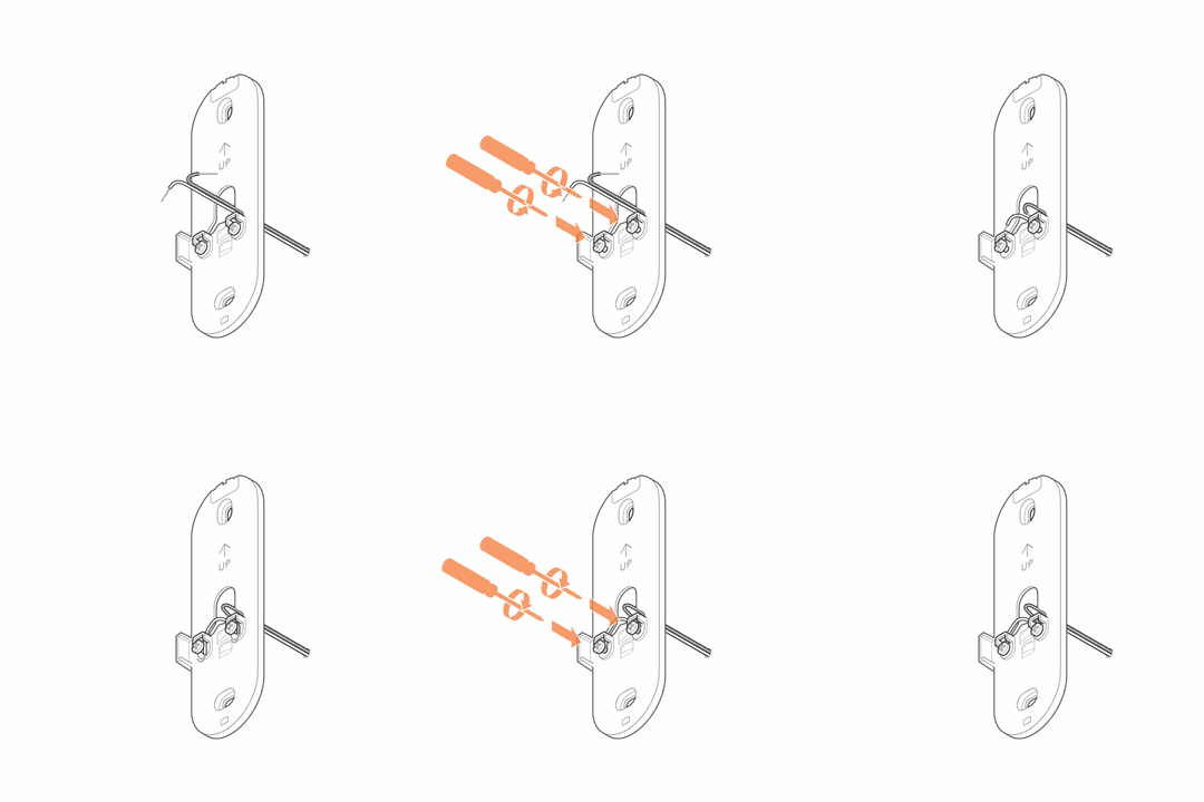
Important: Minimize the length of excess wire leads protruding from the area surrounding the screw terminals. Excess wire can interfere with the assembly to the ADC-VDB775 and may result in the device not powering on. - Mount the wallplate to the surface with the provided screws/anchors.
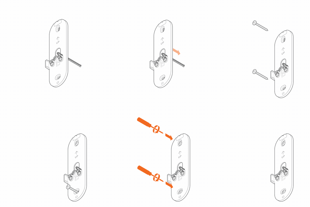
Wedge Mount Kit (ADC-VDBA-775-WMK) steps
Note: Although the 775 Wedge Mount Kit should be sufficient for mitigating most uneven surfaces, the wall spacers are compatible for use in tandem with the Wedge Mount Kit if desired.
If using the wall spacers, remove the black rubber wall spacers from the clear film and firmly attach one spacer near each screw hole on the back of the wedge (i.e., between the wedge and the mounting surface). Do not place the wall spacers between the wedge and the wallplate.
- Thread the wires at the doorbell through the center of the wedge, making sure that the flat side faces the wall. Then mount the wedge to the surface using the provided screws/anchors.
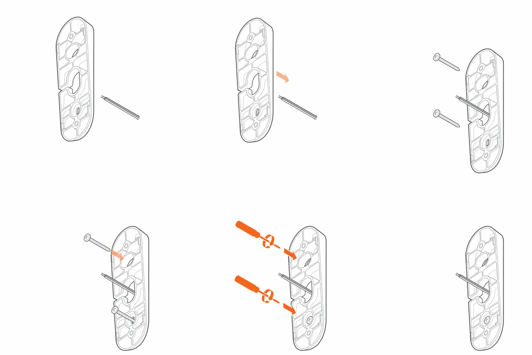
- Secure the wallplate to the mounted wedge using the two machine screws provided with the Wedge Mount Kit.
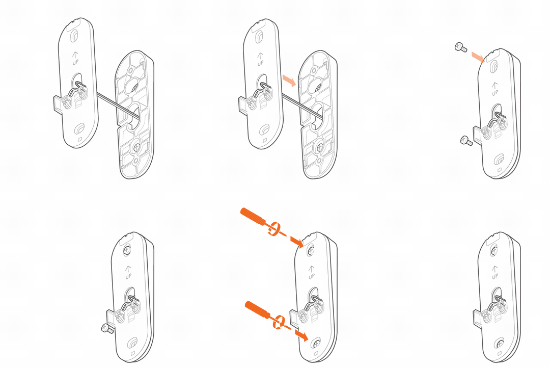
- Thread doorbell wires through wallplate, making sure to thread wires underneath plastic bridges of wallplate leading to screw terminals, and secure to wallplate screw terminals.
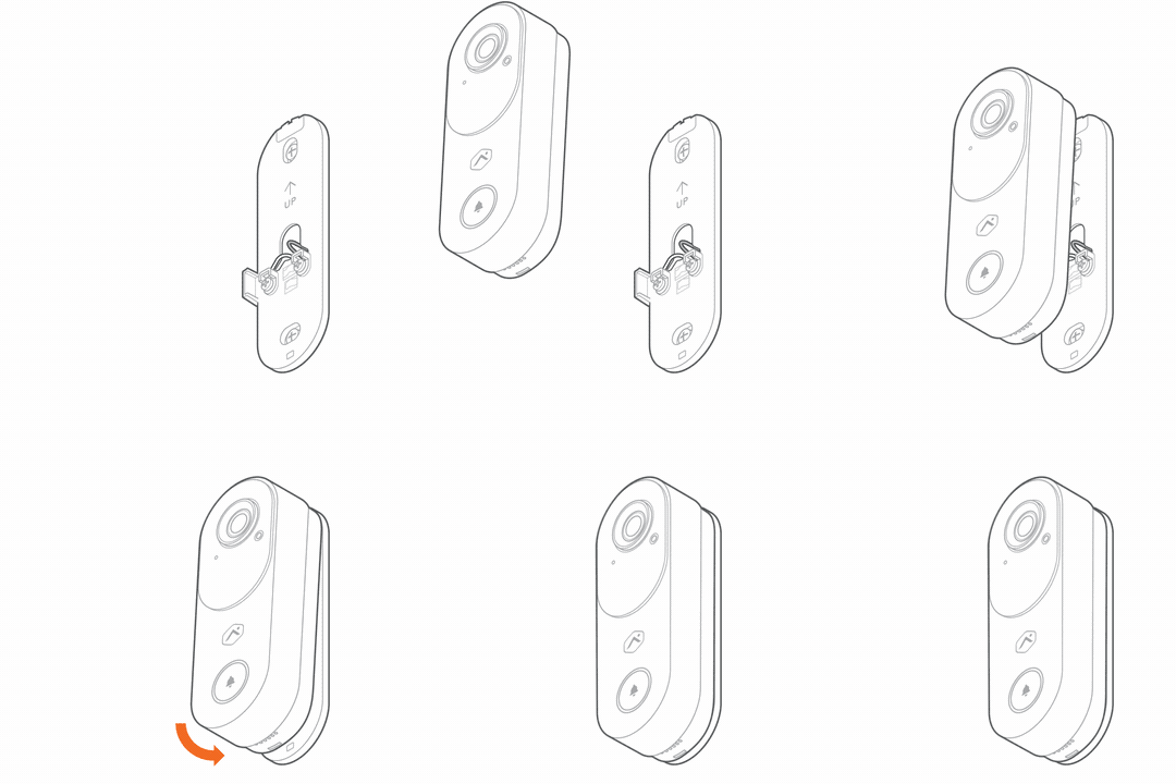
- Connect the ADC-VDB775 to the wallplate by first securing/latching the top edge, then pushing the device into the wallplate until it clicks.
- Restore power to the doorbell circuit (transformer).
Connect the ADC-VDB775 to the Wi-Fi network
The ADC-VDB775 can be connected to the Wi-Fi network using Bluetooth Enrollment (BLE) mode, Access Point (AP) mode, or Wi-Fi Protected Setup (WPS).
Note: An installation tutorial can also be found on the enrollment page of the Partner MobileTech app, Alarm.com app, or Alarm.com customer website to walk through these steps.
BLE mode (recommended) steps
To ensure a sufficient Wi-Fi signal, complete the following steps with the camera near its final location but prior to mounting.
- Connect the camera to power. Verify the device powers on and the LED begins to blink white.
- If it does not blink white after two minutes, press and hold the doorbell button and release when the LED begins to blink white (about 30 seconds).
- On a Bluetooth-enabled mobile device, log in to the Alarm.com app or Partner MobileTech app and complete the following step to add the video device to the customer's account.
To connect devices via BLE mode using the Customer app:

To connect devices via BLE mode using the MobileTech app:
This method will also enroll the device to the customer's account as part of the process.
AP mode steps
- Verify that the device powers on (flashing red LED) and then goes to AP mode (flashing white LED).
- If the LED is not white after two minutes, press and hold the doorbell button and release when the LED begins to blink white (about 30 seconds).
- On an Internet-enabled device, connect to the Wi-Fi network ADC-VDB775 (XX:XX:XX) where XX:XX:XX is the last six characters of the ADC-VDB775’s MAC address, which is located on the device or packaging.
- On the same device, open a web browser and enter http://vdb775install.com or 192.168.1.1 in the URL field. Follow the on-screen instructions to add the ADC-VDB775 to the Wi-Fi network. The LED may briefly turn red before blinking green. The LED will be solid green when the connection is complete.
- Once the LED is solid green, enroll the device to the account using the steps in Enroll the VDB775 to the account.
WPS mode steps
- Verify that device boots (flashing red LED) to AP mode (flashing white LED).
- Press and hold the doorbell button and release when the LED begins to blink blue for WPS mode (about 35 seconds).
- Activate WPS mode on the router. Consult your router’s user guide for more information
- The device will begin to connect to the Wi-Fi network. The LED will be solid green when the connection is complete.
- Once the LED is solid green, enroll the device to the account using the steps in Enroll the VDB775 to the account.
Enroll the VDB775 to the account
The ADC-VDB775 can be enrolled to your customer account using the Alarm.com customer website, or Alarm.com app.
Alarm.com customer website steps
- Navigate to the Video Device Setup page by entering the following URL using a web browser: www.alarm.com/addcamera. The customer's username and password for the account are required to log in.
- If the installation tutorial was used, it automatically navigates to this page after completing the tutorial.
- Enter the MAC address, which is located on the device or packaging, and then click Find.
- Enter a name for the device, then click Install.
- Follow the on-screen instructions to finish adding the camera. An installation progress bar displays on the screen.
Once the installation is complete, test the device to verify it is working as expected.
Alarm.com app steps
- Log in to the Alarm.com app. You will need the username and password of the account to log in.
- Tap
 .
- Tap Add Device.
- Tap Doorbell Camera.
- If the device LED is not solid green, tap ADC-VDB775 for the installation tutorial. If the device is already connected to Wi-Fi and has a solid green LED, continue to the next step.
- Tap Enter MAC Address, then enter the camera's MAC address, which is located on the device or packaging.
- Tap Install for the camera on the Device Found page.
- Enter a device name, then tap Next.
- Follow the on-screen instructions to finish adding the camera. The installation progress displays on the screen.
Once the installation is complete, test the device to verify it is working as expected.
Video doorbell notifications and automation rules with an Alarm.com Chime
For steps and information about creating video doorbell notifications and automation rules with an Alarm.com Chime, see Configure the chime settings for an Alarm.com Video Doorbell and Alarm.com Chime.
LED reference guide
| LED pattern | Description |
|---|---|
|
Off
|
Power off |
|
Solid green
|
Connected to Alarm.com |
|
Blinking green
|
Local network connection |
|
Blinking red
|
Power on, camera booting |
|
Solid red
|
No local or internet connection |
|
Blinking blue and green
|
Firmware updating |
|
Blinking white
|
Bluetooth Enrollment mode and Wi-Fi Access Point mode (press and hold the reset button for 30-35 seconds) |
|
Blinking blue
|
WPS mode (press and hold button for 35-40 seconds) |
|
Blinking yellow
|
Power cycling (press and hold button for 40-45 seconds) |
|
Blinking red and green
|
On all firmware versions:
On firmware version 04023+:
|
|
Blinking yellow and white
|
On firmware version 04023+:
|
|
Blinking blue and white
|
On firmware version 04023+:
|
|
Blinking red and blue
|
Perimeter Guard camera light alert activation |


Troubleshooting
- If you have issues connecting the camera to the account, power cycle the camera and try again.
- If issues persist, reset the camera to factory defaults. Press and hold the Doorbell Button until the LED is flashing green and red (about 45 seconds), then release the button. The camera will reboot to factory default.
If the camera was previously installed on a different Alarm.com account, it will need to be deleted before it can be installed again.
Caution: Prolonged exposure to sunlight in extreme conditions may impact the camera’s performance.
Regulatory statements
Operating Temperature: -58°F - 122°F (-50°C - 50°C)
Ingress Protection: IP65
FCC statements
FCC Part 15 Statement
Note: This equipment has been tested and found to comply with the limits for a Class B digital device, pursuant to part 15 of the FCC Rules. These limits are designed to provide reasonable protection against harmful interference in a residential installation. This equipment generates, uses and can radiate radio frequency energy and, if not installed and used in accordance with the instructions, may cause harmful interference to radio communications. However, there is no guarantee that interference will not occur in a particular installation.
If this equipment does cause harmful interference to radio or television reception, which can be determined by turning the equipment off and on, the user is encouraged to try to correct the interference by one or more of the following measures:
- Reorient or relocate the receiving antenna.
- Increase the separation between the equipment and receiver.
- Connect the equipment into an outlet on a circuit different from that to which the receiver is connected.
- Consult the dealer or an experienced radio/TV technician for help.
- Changes or modifications not expressly approved by the party responsible for compliance could void the user‘s authority to operate the equipment.
FCC ID
FCC ID: YL6-143VDB775
ISED Statements
Condition
This device contains license-exempt transmitter(s)/receiver(s) that comply with Innovation, Science and Economic Development Canada's licence-exempt RSS(s). Operation is subject to the following two conditions:
- This device may not cause interference.
- This device must accept any interference, including interference that may cause undesired operation of the device.
The device operating in the 5150–5250 MHz band is intended for indoor use only.
Cet appareil contient des émetteurs/récepteurs sans licence qui sont conformes aux RSS sans licence d'Innovation, Sciences et Développement économique Canada. L’exploitation est soumise aux deux conditions suivantes :
- Cet appareil ne doit pas provoquer d'interférences.
- Cet appareil doit accepter toute interférence, y compris les interférences susceptibles de provoquer un fonctionnement indésirable de l'appareil.
Le dispositif fonctionnant dans la bande de fréquences 5150–5250 MHz est destiné uniquement à une utilisation intérieure.
RF Exposure
This equipment complies with FCC and ISED radiation exposure limits set forth for an uncontrolled environment. This equipment should be installed and operated with a minimum distance of 20cm between the equipment and your body. This device and its antenna(s) must not be co-located or operating in conjunction with any other antenna or transmitter. Please contact intsupport@alarm.com for more information on Canadian RF exposure compliance.
RF Exposure
Cet appareil est conforme aux limites d'exposition aux radiofréquences établies par la FCC et l’ISED pour un environnement non contrôlé. Cet appareil doit être installé et utilisé à une distance minimale de 20 centimètres entre l’appareil et votre corps. Cet appareil et son ou ses antennes ne doivent pas être situés ou fonctionner en conjonction avec une autre antenne ou un autre émetteur. Veuillez communiquer avec intsupport@alarm.com pour obtenir plus d’information sur la conformité aux exigences canadiennes en matière d’exposition aux radiofréquences.
IC ID
IC: 9111A-143VDB775