
MR50 Single Reader Expansion Module (ADC-AC-MR50) - Installation Guide
Notice: Installation and maintenance servicing for this device should only be performed by qualified personnel.
Note: This article specifically covers the installation of the MR50 Single Reader Expansion Module (ADC-AC-MR50). For instructions on how to set up a broader access system, see Smarter Access Control - Quick Start Guide.
The ADC-AC-MR50 Single Reader Expansion Module provides a solution for interfacing to one Wiegand or OSDP reader and door hardware. It also provides LED control and buzzer control. Two Form-C contact relay outputs may be used to control locking hardware. The two inputs provided can be used for monitoring door contacts and request to exit devices. Input circuits can be configured as unsupervised or supervised using end of line resistors. Communication to the Alarm.com Door Controller is accomplished using a 2-wire RS-485 interface. The ADC-AC-MR50 requires 12 to 24V DC for power.

Note: Newer ADC-AC-MR50 boards may have a J602 jumper used for OSDP termination.
Note: It is recommended to power an ADC-AC-MR50 with 12v DC as power is passed through to the reader device. It is not recommended to power the ADC-AC-MR50 with 24v DC, as most access control readers have a power input rating of 5-16v DC.
Wiring
Connections
| TB1-1 | TR+ | RS-485 Bus |
| TB1-2 | TR- | RS-485 Bus |
| TB1-3 | GND | RS-485 Bus |
| TB2-1 | VIN | Input Power |
| TB2-2 | GND | Input Power Ground |
| TB2-3 | I2 | Input 2 |
| TB2-4 | I2 | Input 2 |
| TB2-5 | I1 | Input 1 |
| TB2-6 | I1 | Input 1 |
| TB3-1 | NC | Relay K1 - Normally Closed Contact |
| TB3-2 | C | Relay K1 - Common Contact |
| TB3-3 | NO | Relay K1 - Normally Open Contact |
| TB3-4 | NO | Relay K2 - Normally Open Contact |
| TB3-5 | NC | Relay K2 - Normally Closed Contact |
| TB3-6 | C | Relay K2 - Common Contact |
| TB4-1 | GND | Reader Ground |
| TB4-2 | BZR | Reader Buzzer Output |
| TB4-3 | LED | Reader LED Output |
| TB4-4 | CLK/D1 | Reader CLK/Data 1 |
| TB4-5 | DAT/D0 | Reader DAT/Data 0 |
| TB4-6 | VO | Reader Power Output |
Wiring an ADC-AC-MR50 for communication and power
Note: It is recommended to power an ADC-AC-MR50 with 12v DC as power is passed through to the reader device. It is not recommended to power the ADC-AC-MR50 with 24v DC, as most access control readers have a power input rating of 5-16v DC.

Wiring multiple expansions for communication and power
While the pictured examples below show how to wire two ADC-AC-MR50 expansions to a Door Controller (ADC-ACC1-17), LP1501 PoE Door Controller (ADC-AC-LP1501), and LP1502 Door Controller (ADC-AC-LP1502), ADC-ACX2 expansion boards may be used in their place as long as you do not exceed eight total expansions per controller.
Note: When using multiple expansions you will need to also address them accordingly. For more information, see Which DIP switches need to be addressed on the MR50 Single Reader Expansion Module (ADC-AC-MR50)? or Which address DIP switches need to be installed on the Two Reader Expansion Module (ADC-ACX2)?.
ADC-ACC1-17 or ADC-AC-LP1501

ADC-AC-LP1502

Status LEDs
Power-up:All LEDs OFF. |
Initialization:Once power is applied, initialization of the module begins. The A LED is turned ON at the beginning of initialization. |
Run time:After a successful initialization, the LEDs have the following meanings:
|
|


Communication wiring
The ADC-AC-MR50 communicates to an Alarm.com door controller using a multi-drop 2-wire RS-485 interface. Shielded cable of 24 AWG with characteristic impedance of 120Ω is specified for the 2-wire RS-485 interface. The total cable length is limited to 4,000 feet (1219 m).
If the ADC-AC-MR50 is the last device on the communication bus, jumper J1 on S2 models or jumper J601 on S3 models must be installed.
Note: The MR50 RS-485 communication wiring is limited by the host controller's maximum run. For more information about the controller's recommended wire gauge and cable length limitations, see Which wire gauge should be used with Access Control Expansion Modules?.
ADC-ACC1-17 / ADC-AC-LP1501
Up to eight total expansion modules may be wired. The last expansion module on the bus must have the end of line termination jumper installed. The end of line termination jumper is J1 for ADC-AC-MR50 Single Reader Expansion Modules and J4 for ADC-AC-MR52 Two Reader Expansion Modules.

ADC-AC-LP1502
Up to sixteen total expansion modules may be wired. The last expansion module on the bus must have the end of line termination jumper installed. The end of line termination jumper is J1 for ADC-AC-MR50 Single Reader Expansion Modules and J4 for ADC-AC-MR52 Two Reader Expansion Modules.
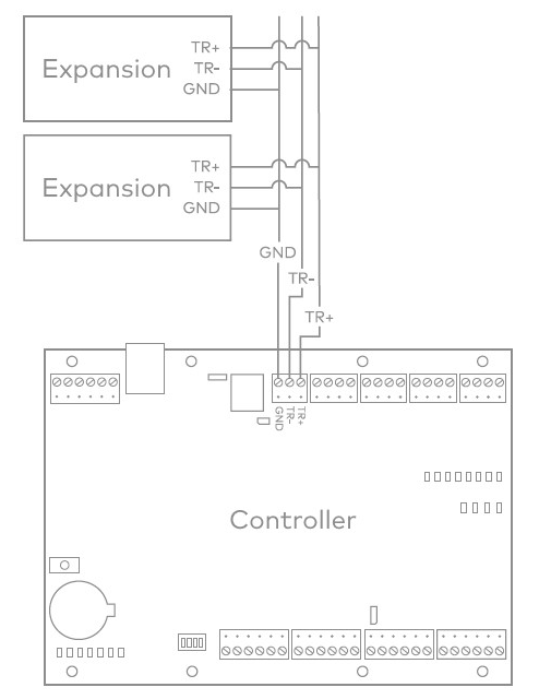
For ease of install, daisy chain expansion modules together. Wire each expansion module to the next module instead of wiring directly back to the controller.
Addressing
Adjust the DIP switches on the ADC-AC-MR50 expansion module according to the Jumpers/Switches ON column in the Access Control Devices table on the Alarm.com Partner Portal. These DIP switches are also displayed in the Add Expansion Module installation wizard. If these DIP switches are not installed according to the website, the device and its connected reader and door hardware will not function properly with Alarm.com.
For more information, see Which DIP switches need to be addressed on the MR50 Single Reader Expansion Module (ADC-AC-MR50)?.
Reader wiring
The reader port supports one Wiegand or OSDP reader. Readers with power requirements different from the input voltage used for the ADC-AC-MR50 board must be powered separately. 22 AWG minimum recommended for readers.
Note: Newer ADC-AC-MR50 boards may have a J602 jumper used for OSDP termination. When using a reader set for OSDP communication, this jumper must be on. When using Wiegand communication, this jumper needs to be removed.
Reader wiring diagrams
Typical Wiegand reader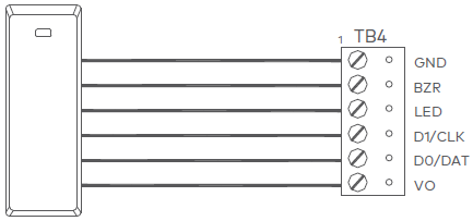
Typical OSDP reader
The input power is passed through to the reader terminal strip and is available for powering a reader. Care must be taken to ensure that the input voltage is within the voltage range of the reader. The reader power output terminal, TB4-6 (VO), is not current limited.
Relay wiring
Two Form-C contact relays are provided for controlling door lock mechanisms. Each relay has a Common pole (C), a Normally Open pole (NO), and a Normally Closed pole (NC). When momentarily delivering power to unlock the locking hardware (fail secure), the Normally Open and Common poles are used. When momentarily removing power to unlock the locking hardware (fail safe), the Normally Closed and Common poles are used. Check with local building codes for proper egress door installation. 18 AWG minimum recommended for electric locking hardware.
The current ratings are 5 A for relay K1 and 1 A for relay K2. Load switching can cause abnormal contact wear and premature contact failure. Switching of inductive loads (strike) also causes EMI (electromagnetic interference), which may interfere with normal operation of other equipment. To minimize premature contact failure and to increase system reliability, a contact protection circuit may be used.
The following circuit is recommended. Locate the protection circuit as close to the load as possible (within 12 inches [30 cm]), as the effectiveness of the circuit will decrease if it is located far away.
Typical DC Door Strike wiring
An electrified door strike replaces a traditional door strike for an Access Control system. Door strikes are predominantly Fail-Secure devices, meaning the door remains secure in the event power is removed. This hardware should be wired as Normally Open using an NO terminal as indicated on Fail-Secure wiring diagram above. This is because entry through the door is only granted when the controller is signaled to close the circuit which energizes the strike and allows entry.
Door lock mechanisms can generate EMF feedback to the relay circuit that can cause damage and premature failure of the relay. For this reason, it is recommended that either a diode or MOV (metal oxide varistor) be used to protect the relay. The wire should be of sufficient gauge to avoid voltage loss.
Diode selection:
Typical Maglock wiring
An electromagnetic lock or maglock is a is an electromagnet which mounts on a door frame, with a steel armature mounted on the door. Maglocks are Fail-Safe only devices. This means that when power is removed or in the event of a fire alarm input (FAI) signal the maglock unlocks the door as required by code. This hardware should be wired as Normally Closed using an NC terminal as indicated on the Fail-Safe diagram above. This is because constant flowing power is required to keep the maglock energized to secure the door.
MOV selection:
Input wiring
There are 8 inputs that are typically used to monitor door position or request to exit devices. Input circuits can be configured as Unsupervised (2 states); reporting as open or closed contact, or Supervised (6 states); reporting as open or closed contact, open circuit, shorted circuit, grounded circuit _, or foreign voltage_.
A supervised input circuit requires adding two resistors with value of 1k ohm, 1% to the circuit to facilitate proper reporting and should be located as close to the sensor as possible.
Note: Grounded and foreign voltage states are not a requirement of UL 294 and therefore not verified by UL.
The input circuit wiring configurations shown are supported but may not be typical.
22 AWG minimum required for input wiring. 18 AWG recommended if wiring request-to-exit devices in series with locking hardware.

Typical Maglock wiring
Specifications
The Expansion Module is for use in low voltage, class 2 circuits only.
Input power
12/24V DC, 150mA max.
110mA nominal @ 12V
60mA nominal @ 24V
Output power
Input voltage pass-through
Communication
2-Wire RS-485
Inputs
One dedicated reader input
Two programmable inputs
One dedicated tamper input
Outputs
Two relay outputs (5A @ 30V DC)
Single-wire LED control
Single-wire buzzer output
Certifications
UL 294 recognized
CE compliant
RoHS
Dimensions (L X W X H )
2.75 x 4.25 x 1.0" (70 x 108 x 25.4 mm)
Temperature
-40 – 167°F (-40 – 75°C) operational
-67 – 185°F (-55 – 85°C) storage
Operating humidity
5-95% (non-condensing) RH
Warranty
Mercury Security warrants the product is free from defects in material and workmanship under normal use and service with proper maintenance for one year from the date of factory shipment. Mercury Security assumes no responsibility for products damaged by improper handling or installation. This warranty is limited to the repair or replacement of the defective unit.
There are no expressed warranties other than set forth herein. Mercury Security does not make, nor intends, nor does it authorize any agent or representative to make any other warranties, or implied warranties, and expressly excludes and disclaims all implied warranties of merchantability or fitness for a particular purpose.
Returns must be accompanied by a Return Material Authorization (RMA) number obtained from customer service, and prepaid postage and insurance.
Liability
The Interface should only be used to control exits from areas where an alternative method for exit is available. This product is not intended for, nor is rated for operation in life-critical control applications. Mercury Security is not liable under any circumstances for loss or damage caused by or partially caused by the misapplication or malfunction of the product. Mercury Security's liability does not extend beyond the purchase price of the product.

This device complies with part 15 of the FCC Rules. Operation is subject to the following two conditions: (1) This device may not cause harmful interference, and (2) this device must accept any interference received, including interference that may cause undesired operation.